Greenhouse-eXactum concept / by Timo Hyyppä
Code: https://github.com/Hakkarainen/greenho
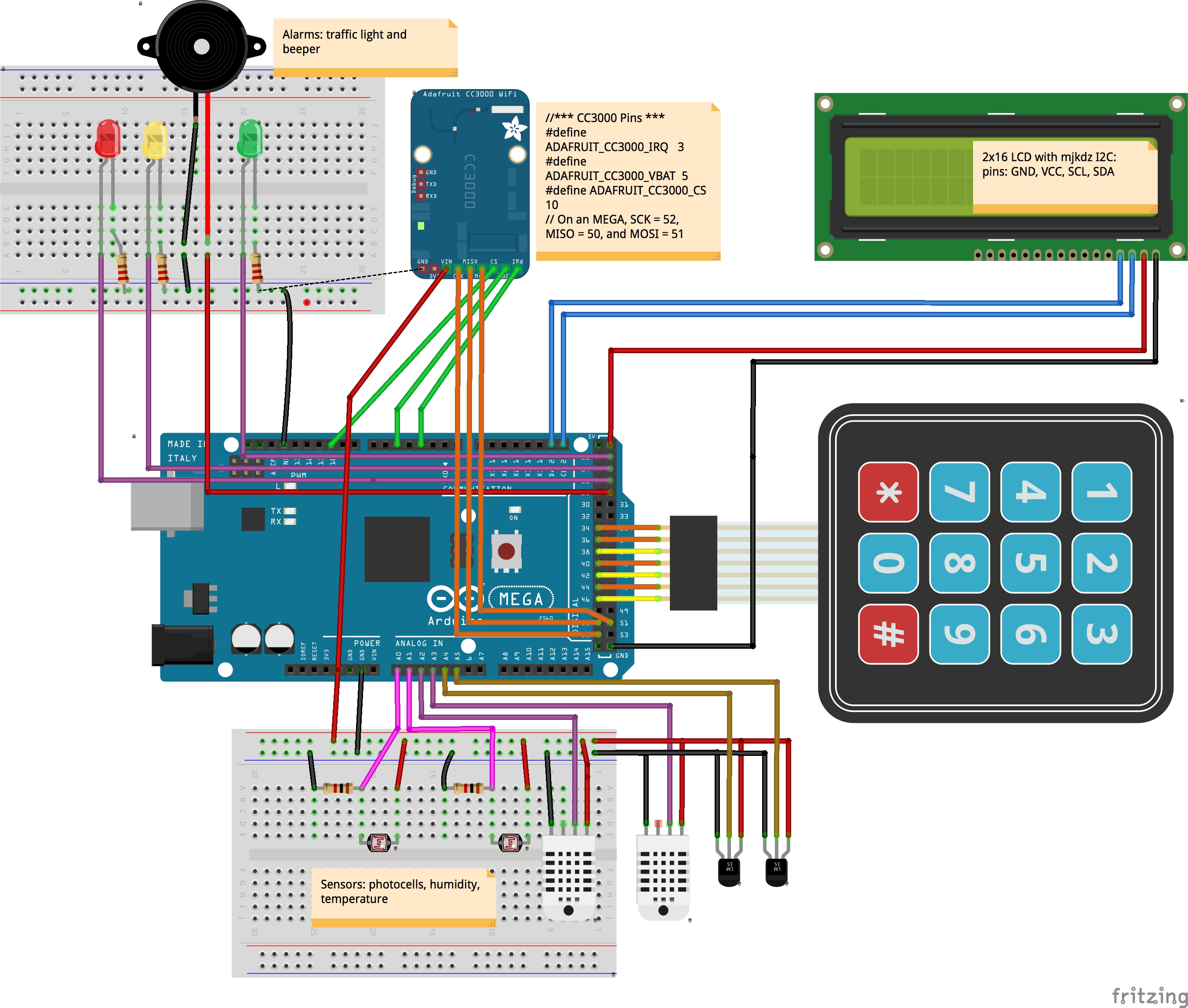
HW-Components:
Application:
The application has six parts:
1. Sensor-handling and configuration management
2. Alarm-generation and processing
3. NTP-time stamping
4. Local statistics and reporting
5. sensor analytic on remote web-dash board.
6. MQTT-based network communication
1. Sensor-handling and configuration management
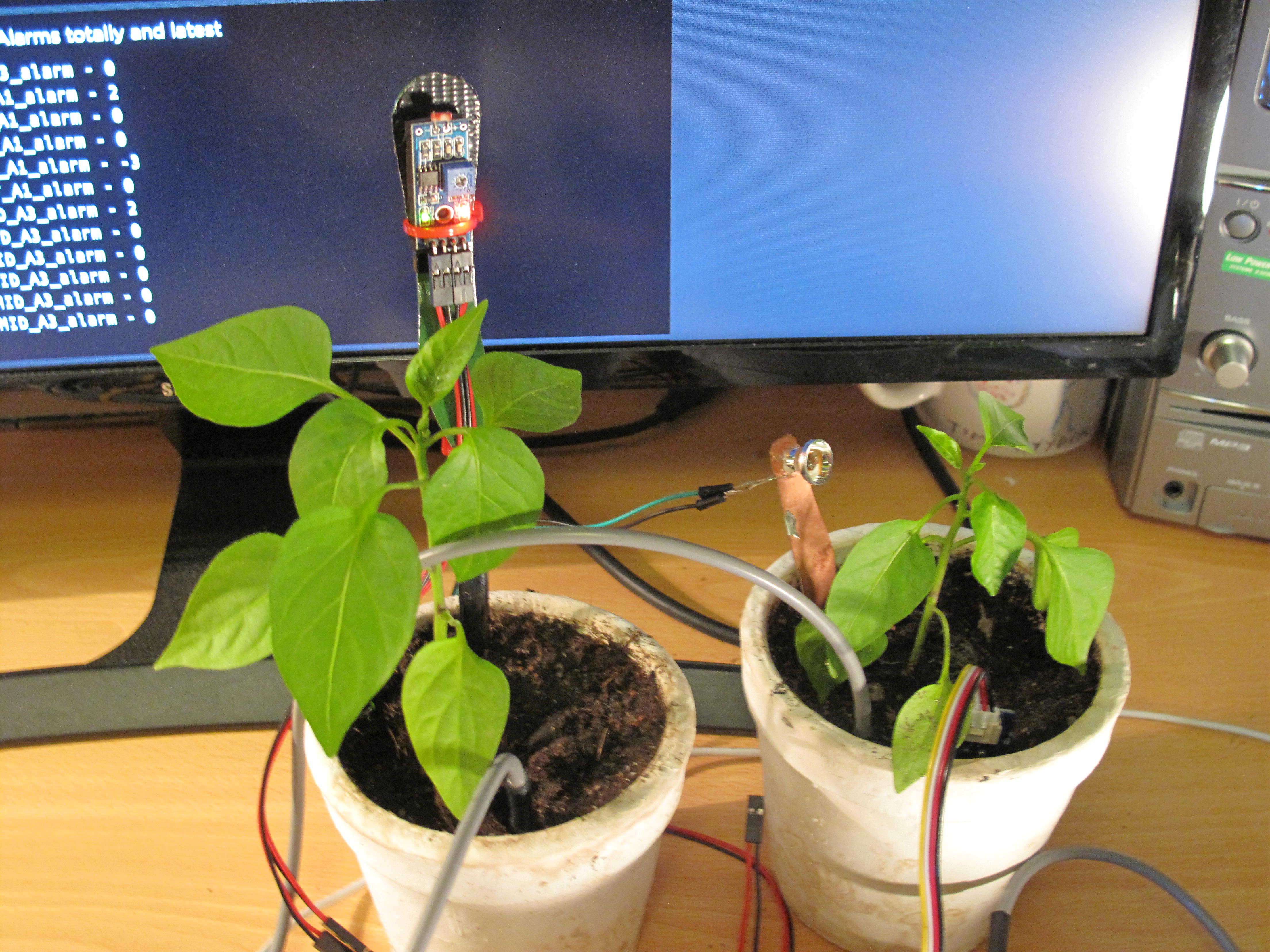
Sensors are connected to analog-inputs A0-A5 of Arduino Mega. There are three kind of sensors: photocells, humidity- and temperature sensors. The sensors are calibrated by using the measurement values of a reference plant-pot as reference levels. If the conditions of a reference plant are changed drastically, new reference values are read automatically and averaged as reference levels for the sensors in other plant-pots . Each plant type has two kind of profiles (soil and air) defined in
relativistic manner when comparing to the reference levels of the reference plant.
All measurements are based on several readings with a proper delay in between and those are averaged. If measurements are out of range at many sensors repeatedly, a re-calibration of sensors is executed automatically. The time dependent functionalities of the sensor measurements are parametrized and thus can be adjusted according to needs.
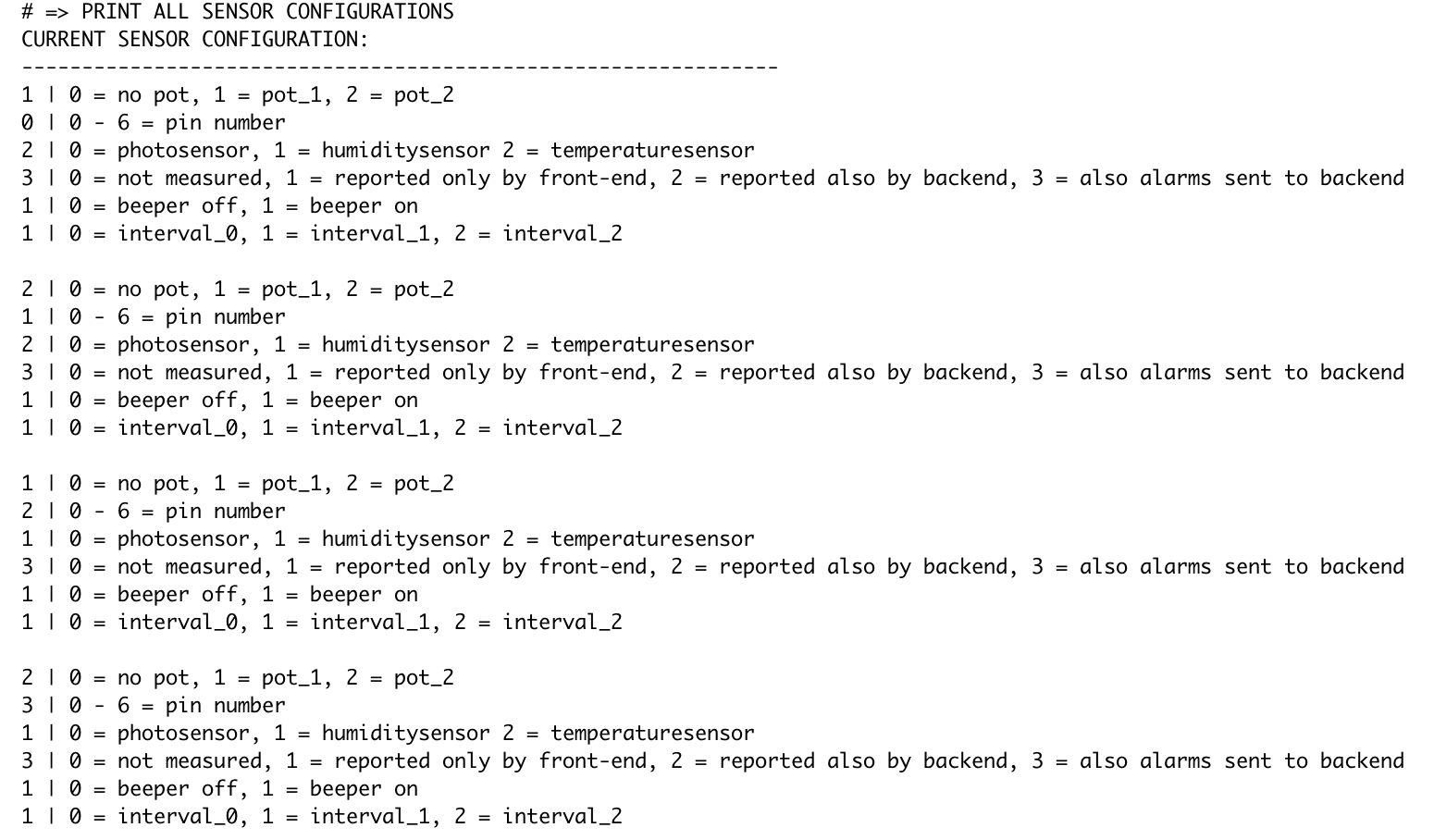
The number of sensors can be set and their functionalities and connections can be managed. An example configuration application is implemented in the demo, which also prints the current and modified configurations on the console (per sensor and all sensors) for user review.
All sensor measurements can be sent to the backend cloud via a publish/subscribe protocol (MQTT) for the pot-specific dash board application. System can also be configured per sensor in a mode which makes only local statistics without the need for network communication for the remote dash board.

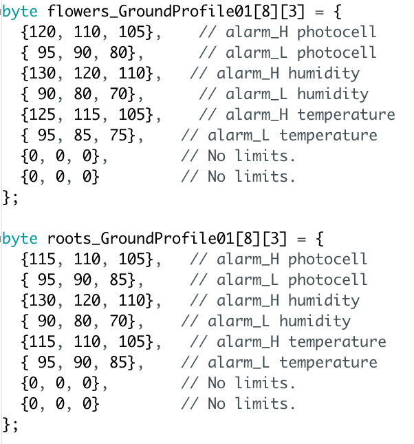
2. Alarm-generation and processing
Each plant type have specific profiles which define the optimal life conditions (measurement ranges) for it. There are both soil and air profiles for the plant type and three relativistic zones (green, yellow and red) are defined above and below the reference plant levels. After measurement it is analyzed and classified by the alarm-application and also cumulative alarm-statistics are maintained and printed out on console locally.
Alarms are reported to the user via a traffic light-like LED-based display and a beeper. Number of beeps and the pitch of the signal ending tone informs the user about which zone the measurement belongs to and how serious the alarm is. The green zone does not generate any sound, The beeper can be set on or off by the user. Alarms are also sent to the backend cloud via a publish/subscribe protocol (MQTT) for the pot-specific dash board application.
For the local serial monitor the alarms are printed as clear console-text, which gives to the user information about the seriousness of the alarm and some proposals for corrective care actions.
3. NTP-time stamping
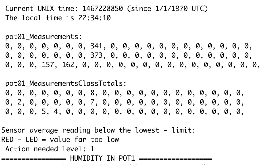
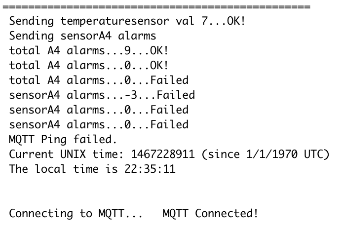
The system keeps track of correct time-stamping via NTP-protocol which fetches the official Internet time (Unix-time) in seconds when ever needed. Unix time is converted also into local time for the reporting on the console.
4. Local statistics and reporting
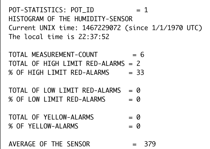
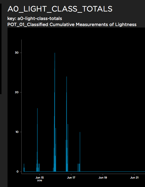
The system classifies the measurements into selected number of classes configured during the system installation. The last classified measurements and cumulative statistics are stored locally for console reporting. Measurement statistics and also histograms covering longer periods are available. Alarms are reported respectively per alarm zones.
5. Sensor analytic on remote web-dash board.
The remote web-dash board application supports creation of sensor and alarms based publish/subscribe-information feeds and configuring of a set of selected UI-components which are able to process the data feed inputs for user. The dash board UI-components are able to draw graphs at selected time interval scale and in real time. New feeds and UI-components can be created and existing ones updated or removed. If a new subscription feed is created at dash board end it needs definition of its publishing counterpart in the Arduino end and vice versa is true if a new publisher is defined in the Arduino end.
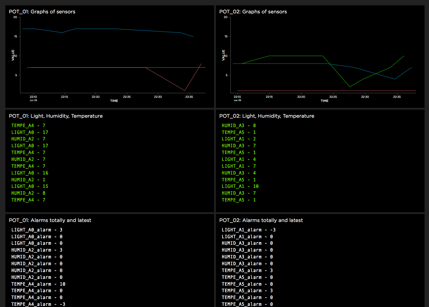
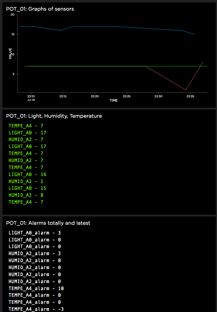
In the demo the pot-specific sensor measurements are displayed as realtime sensor-graphs and also cumulative class-histograms. The sensor specific alarms are displayed in real time as pot-specific lists. The dash board allows flexible configuration change and information presentation capabilities.
https://io.adafruit.com/dashboards
6. MQTT-based network communication
Why MQTT IoT-protocol ?
https://learn.adafruit.com/mqtt-adafruit-io-and-you/why-mqtt
MQTT IoT-protocol:
http://mqtt.org/faq
6.1 This Greenhouse-project uses:
https://learn.adafruit.com/mqtt-adafruit-io-and-you/intro-to-adafruit-mqtt
Publish & Subscribe protocol / Adafruit-concept:
With MQTT the Greenhouse system can publish data to the MQTT-broker, and also subscribe data from the MQTT-broker.
Adafruit CC3000 wifi + MQTT:
https://www.adafruit.com/products/1469
https://github.com/adafruit/Adafruit_MQTT_Library/blob/master/examples/mqtt_cc3k/cc3000helper.cpp
Libraries needed:
#include “Adafruit_MQTT_CC3000.h”
#include “Adafruit_MQTT.h”
#include “Adafruit_MQTT_Client.h”
/*** Adafruit.io Setup ***
#define AIO_SERVER “io.adafruit.com”
#define AIO_SERVERPORT 1883
#define AIO_USERNAME “…your AIO username (see https://accounts.adafruit.com)…”
#define AIO_KEY “…your AIO key…”
// Store the MQTT server, username, and password in flash memory.
// This is required for using the Adafruit MQTT library.
const char MQTT_SERVER[] PROGMEM = AIO_SERVER;
const char MQTT_USERNAME[] PROGMEM = AIO_USERNAME;
const char MQTT_PASSWORD[] PROGMEM = AIO_KEY;
// Setup the CC3000 MQTT class by passing in the CC3000 class and MQTT server and login details.
Adafruit_MQTT_CC3000 mqtt(&cc3000, MQTT_SERVER, AIO_SERVERPORT, MQTT_USERNAME, MQTT_PASSWORD);
Greenhouse-project implementation using io.adafruit:
Greenhouse-project libraries for connectivity:
#include <Adafruit_SleepyDog.h>
#include <Adafruit_CC3000.h>
#include <SPI.h>
#include “utility/debug.h”
#include “Adafruit_MQTT.h”
#include “Adafruit_MQTT_CC3000.h”
#include <ccspi.h>
/*** Feed examples used in Greenhouse project ********************/
// Setup a feed called ‘lightsensorA0’ for publishing.
// Notice MQTT paths for AIO follow the form: <username>/feeds/<feedname>
const char LIGHT_A0[] PROGMEM = AIO_USERNAME “/feeds/LIGHT_A0”;
Adafruit_MQTT_Publish lightsensorA0 = Adafruit_MQTT_Publish(&mqtt, LIGHT_A0);
// Setup a feed called ‘humiditysensorA2’ for publishing.
const char HUMID_A2[] PROGMEM = AIO_USERNAME “/feeds/HUMID_A2”;
Adafruit_MQTT_Publish humiditysensorA2 = Adafruit_MQTT_Publish(&mqtt, HUMID_A2);
// Setup a feed called ‘temperaturesensorA4’ for publishing.
const char TEMPE_A4[] PROGMEM = AIO_USERNAME “/feeds/TEMPE_A4”;
Adafruit_MQTT_Publish temperaturesensorA4 = Adafruit_MQTT_Publish(&mqtt, TEMPE_A4);
// Alarm-feeds
// Setup a feed called ‘lightsensorA0alarm’ for publishing.
const char LIGHT_A0_alarm[] PROGMEM = AIO_USERNAME “/feeds/LIGHT_A0_alarm”;
Adafruit_MQTT_Publish lightsensorA0alarm = Adafruit_MQTT_Publish(&mqtt, LIGHT_A0_alarm);
// Setup a feed called ‘humiditysensorA2alarm’ for publishing.
const char HUMID_A2_alarm[] PROGMEM = AIO_USERNAME “/feeds/HUMID_A2_alarm”;
Adafruit_MQTT_Publish humiditysensorA2alarm = Adafruit_MQTT_Publish(&mqtt, HUMID_A2_alarm);
// Setup a feed called ‘temperaturesensorA4alarm’ for publishing.
const char TEMPE_A4_alarm[] PROGMEM = AIO_USERNAME “/feeds/TEMPE_A4_alarm”;
Adafruit_MQTT_Publish temperaturesensorA4alarm = Adafruit_MQTT_Publish(&mqtt, TEMPE_A4_alarm);
// TOTALS FOR HISTOGRAMS FEEDS
//Measurement totals-feeds:
// Notice MQTT paths for AIO follow the form: <username>/feeds/<feedname>
const char A0_LIGHT_CLASS_TOTALS[] PROGMEM = AIO_USERNAME “/feeds/A0_LIGHT_CLASS_TOTALS”;
Adafruit_MQTT_Publish A0lightClassTot = Adafruit_MQTT_Publish(&mqtt, A0_LIGHT_CLASS_TOTALS);
//Measurement totals-feeds:
const char A2_HUMID_CLASS_TOTALS[] PROGMEM = AIO_USERNAME “/feeds/A2_HUMID_CLASS_TOTALS”;
Adafruit_MQTT_Publish A2humidClassTot = Adafruit_MQTT_Publish(&mqtt, A2_HUMID_CLASS_TOTALS);
//Measurement totals-feeds:
const char A4_TEMPE_CLASS_TOTALS[] PROGMEM = AIO_USERNAME “/feeds/A4_TEMPE_CLASS_TOTALS”;
Adafruit_MQTT_Publish A4tempClassTot = Adafruit_MQTT_Publish(&mqtt, A4_TEMPE_CLASS_TOTALS);
// END OF FEEDS DEFINITION *****************************************************