Raspberry Pi based automated greenhouse monitoring and watering system
Introduction
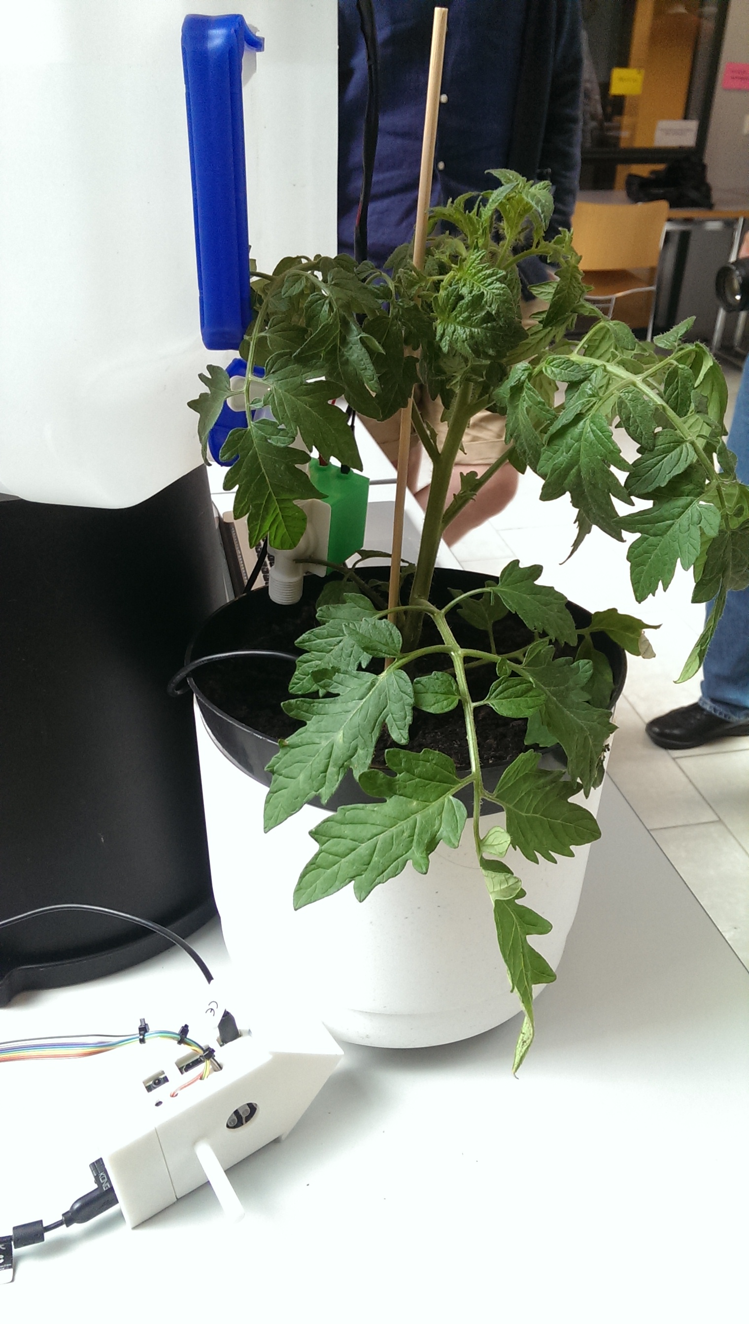
Our original goal with this project was to build an environment where you could leave your plant unattended for weeks at a time. Environment should report the condition of the attached plant, surrounding environment and amount of water left in tank. It should also be able to water the plant automatically based on humidity threshold levels defined. As you’ll see, this last part was not yet achieved.


Hardware
We use Raspberry Pi with Raspbian as a central piece of the system. Main reasons for this is a wide range of on-board connectors, and flexible, well supported Linux operating system with Node.js support.
Logitech webcam for posting photos to Twitter
This is just as simple as connecting it to USB port and installing fswebcam.
Humidity and temperature
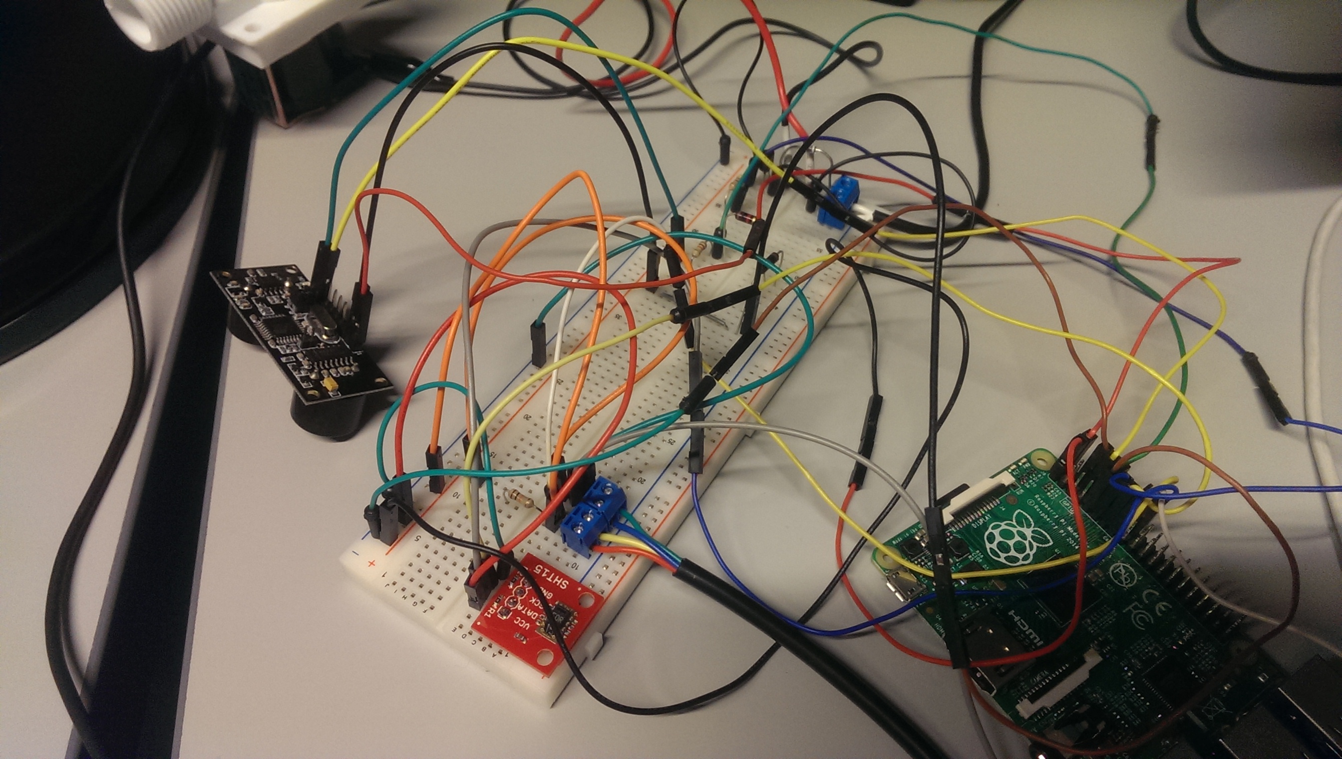
Measure and temperature are measured from both soil and air. Both sensors are manufactured by Sensirion, for soil measurements we use SHT10 in a metal casing, for air measurements SHT15.
There’s supposed to be a huge variation in durability of soil moisture sensors, and SHT10 seems to perform very well. It needs one 10k resistor from data to 3.3V, as seen in wiring diagram. SHT15 is connected straight to RPi.
Water level
Water level is measured with ultrasonic sensor connected inside the roof of the water tank. We use DFRobot URM37 sensor. It requires two resistors connected to TX connector: 1k between TX and RPi’s RX, 2k between 1k and ground.
Water flow
Solenoid is used for controlling water flow. It needs a separate 12V power supply to work. Only a trigger signal is sent from Raspberry Pi. There’s a 400R resistor between GPIO and transistor base. Transistor is NPN transistor 2N3904, diode is 1N4001.
This part requires experimenting, as we couldn’t get stable output from our solenoid before the project deadline. The part was most likely broken as it worked out fine when dry, but stopped after water was put through it.

Software
Frontend
Frontend uses AngularJS with Highcharts to visualize the data. It’s a single page application which we host in Firebase, the same place we store in and read our data from.
There’s a Github repository and Firebase hosting guide to get it all running.
In order to show the saved data, you have to enable certain measurement types. The data is drawn based on sensors object, which lives in your database.
There’s a chart drawn for every child of sensors, and there’s a value drawn for every child of sensors/sensorname/measures. Here’s an example that draws humidity and temperature of air sensor:
“sensors” : {
  “air-temperature-and-humidity” : {
    “measures” : {
      “humidity” : {
        “unit” : “%”
      },
      “temperature” : {
        “unit” : “C”
      }
    }
  }
}
Units are only saved for clarification at the moment.
Next steps with the frontend would be to refactor the code to support data binding, and to improve the performance by limiting number of fetched data points.
Backend
The backend is written using NodeJS and is run as a Forever service. The complete backend code is found in the Github repository. For the SHT1x based sensors (air and soil moisture and temperature) a modified library based on Keitos where support for multiple sensors were added was used. At the current state the sensor data is read periodically and posted to the Firebase service. Also a webcam image is captured and posted to Twitter as a media tweet. However, the solenoid valve is not triggered automatically. One of the reasons for lack of this support is that the valve we had did not work well enough for us to test enough. The next step would be to build a support for this.

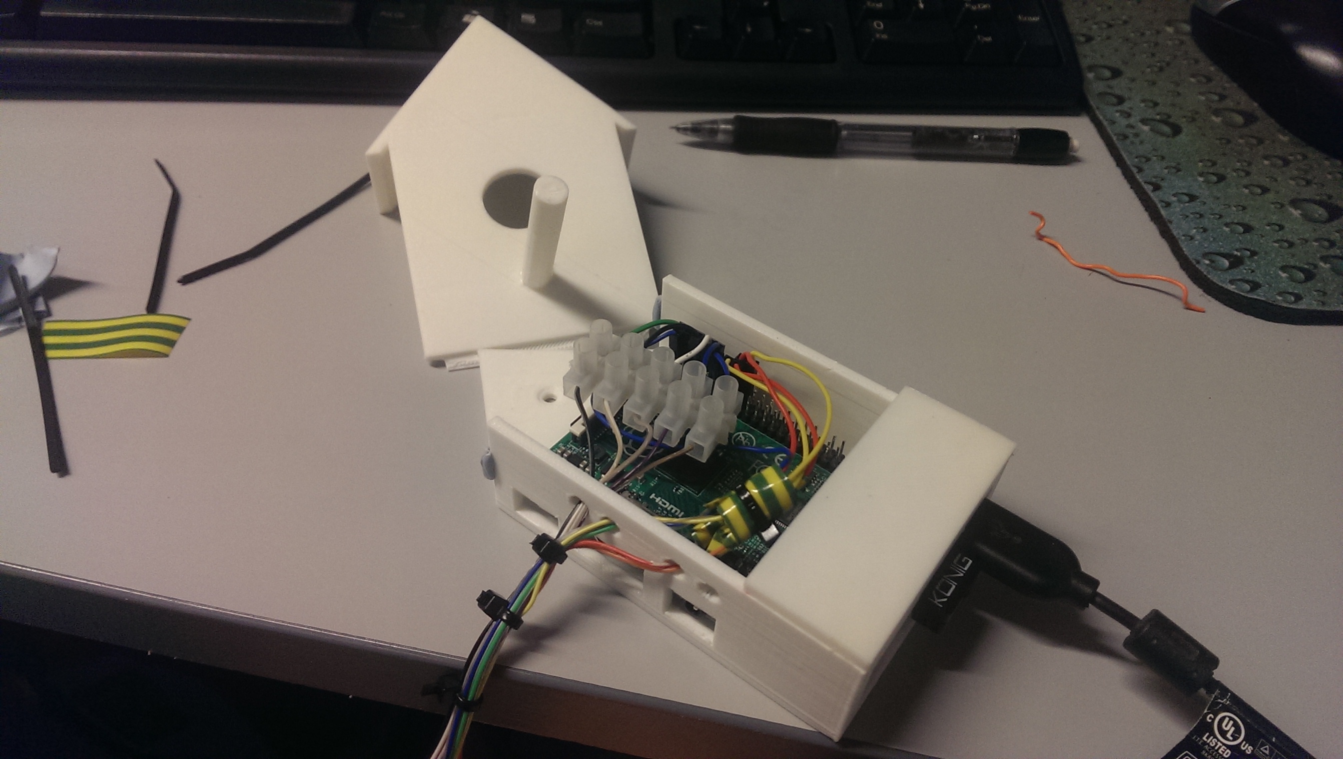
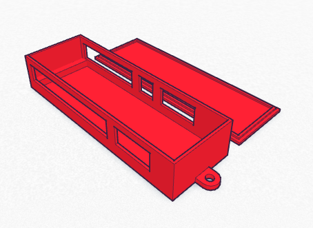
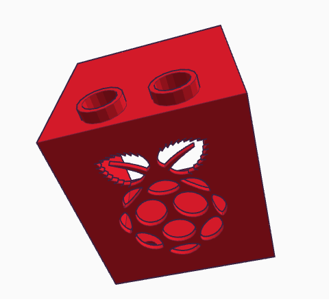
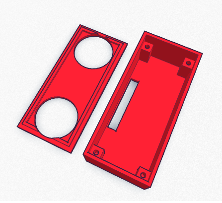
Casing
The casing for the device is designed using the lovely Tinkercad and 3D printed using the MakerBot Replicator 2. Casings were designed for the Raspberry Pi B+, sensor connector PCB, URM37 and solenoid valve. We noticed that the appearance of the complete setup with all the wires going from the main unit to the sensors through the connector unit is quite messy. The design could be improved by either using wireless sensors or designing both the main unit and the connector board in a single unit.
The designs are available in Tinkercad

Team
- Antti Laakso (backend, sensors, 3D design)
- Antti Suniala (frontend, PCB design, soldering)