IoT: Exactum Greenhouse / Project Plantspinner

Overview

Phototropism, basically, causes plants to grow towards the Sun, or other source of light. In many situations, such as with the casual home gardener who grows his/her plants on a window sill, plants only get light from one general direction. As the home gardener turns his/her back to gardening duties just for a few moments (weeks), the plants might have already found their way out of the pot and, without support, creeping around their surroundings and robbing the gardener of their initial visual delight.

There is an easy solution to the problem posed by phototropism: turning the plants every now and then. However, such daunting, repetitive tasks are not for the great minds to trouble themselves with, so, a more automated solution is in order, and that is what we set to build.

Our solution forms around a very simple design using a microcontroller, servo and light sensor. The design has the plant sitting on a rotating platter that can be, ideally, turned to any angle driven by a servo. A light sensor serves to gather information on the amount of light received by the plant during a given period. A simple algorithm in the microcontroller will then rotate the plant so that in a given time frame each side of the plant will receive a similar amount of light.

Plantspinner in action during testing

Plantspinner in action during testing

Hardware Implementation

We used Arduino Yún as the microcontroller of choice, mostly because it happened to be the only microcontroller available; we did not want to use a “real computer” such as Raspberry Pi or one of the similar Intel creations. For learning, a limited platform sounded more interesting. The light sensor we got was a digital one, namely, Adafruit’s TSL2561 and the servo an AAS-752MG High Performance Race Servo (High Speed). The Yún version of Arduino is really nice for the IoT purpose, because it has an integrated WiFi board, meaning much less hassle with getting the project online.

Our prototype (which later ended up being the final version as well) was built inside a shoe box made of cardboard and as such not really suitable for applications involving water – at least,
not for extended periods of time or large amounts of water.

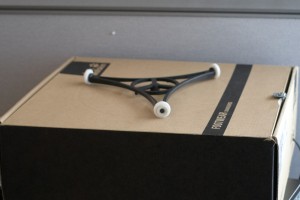
The first problem we faced with the design was that a servo usually only turns 180 degrees whereas we needed close to 360 degrees of movement. The problem was ingeniously solved by using a microwave platter and the wheel system below it to amplify the servo’s amount of rotation. A proper gear system would have been better, but we never got around to building that. A follow-up problem was connecting the servo to the microwave platter’s drive system, and that we solved by 3D printing a suitably sized shaft part and attaching that to the servo with rubber bands – a somewhat crude solution, but the 3D printer’s resolution didn’t seem to suffice for a proper toothed servo attachment. Although, we never got the highest resolution printing to actually work with the PLA filament.

Microwave platter and a shoe box

Microwave platter and a shoe box

The light sensor was taped to a side of the shoe box that faced the light source. The light sensor, being digital, appeared to work fine out-of-the-box, but…on a sunny day the thing decided to overload after all. So, as we only needed relative light readings instead of absolute ones, we fashioned a small shade out of paper for the sensor to limit the incoming light.

Light sensor "filter"

Light sensor “filter”

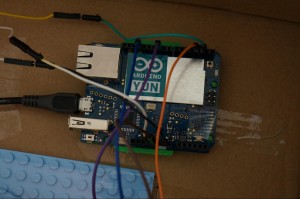
The servo and the light sensor were both connected to the Arduino board as shown in some examples. So, no fancy electronics skills required.

Arduino wiring

Arduino wiring

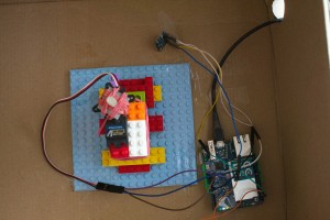
Organization inside the shoe box

Organization inside the shoe box

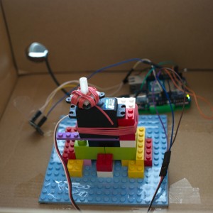
Inside the shoe box: 3D printed servo shaft

Inside the shoe box: 3D printed servo shaft

Software Implementation

We started the Arduino part of the implementation by playing around with example code for the servo and light sensor libraries. Much of the heavy lifting is hidden in the libraries, so driving the servo and reading the light sensor is really easy on the Arduino.

The control logic was created on a less-than-rigorously-scientific basis. The platter was given three possible positions at 0, 120 and 240 degrees – remember that a servo turns to absolute values. The microwave platter system seemed to amplify a turn by approximately 1.6 times, so, the corresponding servo values were 0, 75 and 150 degrees. A day (24 hours) seemed like a sensible period between rotations. Rotating the plant too often would probably disturb the plant as well anyone in the same room as the plant.

The luminosity values are averaged for a short period (20 secs) and then the averages are summed up to get an accumulated value for a day. The accumulated luminosity values as well as the servo positions are saved in a history queue (ten days) and a decision to rotate or not the rotate the platter is made based on the history data: choose the position that has received the least light according to the history – a typical scheduling algorithm in essence.

When the Arduino has connectivity, luminosity and servo position data is uploaded to a database every minute. As a smaller task, the Arduino code also updates its idea of date from the WiFi component once a day. Otherwise there would be clock shift between the microcontroller and the WiFi board (and the real world), which would ultimately prevent database uploads.

We chose to use Amazon DynamoDB as the database backend for this project. There is an example project with source code (googlable) that uses DynamoDB, but after creating the accounts and setting up the DynamoDB database, we found out that the code to do the  required hash calculations for Amazon authentication takes so much space on the Arduino that there is very little left for anything else. The Arduino also seems to start getting unstable when the dynamic memory runs low – so heed the warning given by the Arduino IDE.

We stuck with our choice.

Fortunately, Arduino Yún’s WiFi component has an OpenWrt Linux environment with Python and all that stuff. So, the Amazon hashing and upload was implemented as a Python script and called from the microcontroller side using the Arduino “bridge” interface, leaving proper space for actual program logic in the microcontroller.

Lesson learned: mixing microcontrollers with authenticated REST APIs is plain stupid.

One additional problem faced with the servo was that it was just too fast. An off-center plant might be thrown off the platter. As a solution, the servo control was slowed down by turning the servo one degree at a time towards the chosen next position and inserting a delay of 100 ms in between.

The database frontend was written in python and a Google API was used to draw graphs from the data. Lacking a suitable hosting provider, we ran the prototype web server locally on a laptop.

Web frontend: monthly view

Web frontend: monthly view

Web frontend: daily view

Web frontend: daily view

Testing

The light sensor was tested separately on a sunny week. As the weather has been mostly grey-ish this far, it was lucky to have a few sunny days during the testing period. Testing revealed that the sensor by itself overloaded (producing zero measurement result) when in direct bright sunlight. Therefore, we needed to insert a filter.

The whole system was left running with a plant on it for a week. However, such a short testing period did not really reveal much since plants do not grow that fast. Proper testing would have had a control plant with no rotation sitting near the system and done for at least a month to see the results.

In conclusion

Just before the demonstration, the WiFi password had changed at the department, which we didn’t know, and spent half a day wondering what had gone wrong the Arduino. (The experience did teach something new, though: you can log into the Arduino WiFi component with a Serial console sketch and configure the WiFi with an OpenWrt commandline tool called uci.) Also, at the demonstration, the upload naturally did not work as changed electrical outlets seem to affect WiFi connections or configurations. Just something to consider..

At the demonstration someone remarked that using the microwave platter was the mechanical innovation of the day. Generalising from that remark, the whole project consisted of a rather tight schedule to put together a working system out of some proper parts and lots of duct tape, and as such, coming up with the “duct tape” to bind everything together was the interesting bit.
In a whole system that spans from a light sensor to a cloud-based database, there are lots of technologies involved. One might have to learn from microcontroller programming to REST APIs and from soldering and using mechanical tools to 3D CAD design and 3D printing.

The team:
Yu Zhang – Hardware/mechanical design and implementation, DynamoDB setup, Web frontend
Heikki Lindholm – Arduino programming, 3D design

Video: testing the rotating platter

Video: prototype in action/testing

Source code: database upload (Arduino OpenWrt)

Source code: Arduino sketch

Source code: web page generator script

Modular hydroponics system

Introduction

Hydroponics is a method of growing plants in nutrient solution without soil. Hydroponics is an efficient way of growing plants as nutrients are delivered directly to the roots in soluble form. It enables plants to allocate more resources to leaves, flowers and fruits.

We decided to create a small-scale hydroponics system with constant water flow. There are many such hydroponics systems commercially available, but we wanted to design our own. Our idea was to build a modular system consisting of a nutrient solution tank, a water pump and separate plant containers that could be connected to form a hydroponics system of 1 – 5 plants. Sensors attached to the system would measure temperature, humidity and lightness of the surroundings. Our initial plan also included measuring nitrate concentration of the nutrient solution and adjusting the amount of nutrients according to the measurements. However it turned out that nitrate sensors are expensive and difficult to get, so we gave up that part of the plan. Instead, we used a simple water sensor in the tank to detect when more water was needed.

Component overview

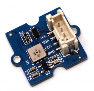
All our sensors were Grove system compatible which means that the sensors could be connected to a Grove Base Shield on top of an Arduino Uno microcontroller without tinkering. We used Grove Luminance Sensor to measure amount of light, Grove Temperature & Humidity Sensor Pro to measure temperature and relative humidity and Grove Water Sensor to detect when the tank was empty. For wireless networking, we used a separate Adafruit CC3000 Wifi Breakout plugged into the base shield. In addition to electronics we had a small Jebao AP-300 aquarium pump.

ghe_bbWiring schema

Sensors and data collection

Grove Water Sensor detects presence of water by measuring conductivity between interlaced sensor traces connected to SIG/VCC pins and ground traces connected to GND pin. When the sensor is exposed to water, conductivity between sensor traces and ground traces increases and voltage value in SIG pin becomes low. Otherwise it is high. We connected the sensor to the base shield’s digital pin and used it as a simple water detector. The sensor could also be used to measure changes in electric conductivity of nutrient solution by connecting it to an analog pin.

Grove Luminance Sensor contains an APDS-9002 lumen sensor . It is a simple analog-output sensor that peaks approximately in wavelength range 400-650 nm. This is very close to the spectrum of human vision. With standard 3.3 V input current, the sensor outputs a value between 0 and 1023 which is converted to voltage by simple arithmetics: output voltage = 3.3 V * output value / 1023 . Voltage values above 2.3 V are inaccurate and mean that the sensor is saturated by light. The output voltage can be linearly transformed to a lux value.

Grove Temperature and Humidity Sensor Pro is a DHT22 sensor with a capacitive humidity sensor and a thermistor. It outputs a 40 bit digital signal consisting of a relative humidity component (8 bit integer + 8 bit decimal), a temperature component in Celsius degrees (8 bit integer + 8 bit decimal) and a checksum (8 bits). Getting data from the sensor requires carefully timed signal exchange between the sensor and the microcontroller. Data request starts by sending the sensor a low voltage signal followed by a high voltage signal and then waiting for a response from the sensor. This is called “handshaking”. The sensor then sends data in a sequence of low and high voltage signals. One bit consists of 50 ms low voltage signal followed by a high voltage signal. The value of of the bit (0 or 1) is determined by the length of the high voltage signal.

We did not need to implement the procedure described above as somebody else had already done it. We used DHTlib to control the sensor. Reading other sensors was straightforward and no external libraries were required.

Sensor data was collected every minute during the testing period and sent to the backend server in a HTTP POST request. We used Adafruit CC3000 library and code samples that came with it to set up the network connection. CC3000 module tended to get stuck when initializing the connection. To avoid it we set up a watchdog: a timer that resets the system if the timer is not reset in eight seconds.
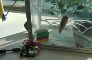
ANjOkhGwtKeHJBfaWDeM-Zs2oNZgGsFZpmXiVtJo-_Zu9fHUlwzchFxmw78ETEJt4-3xK9cLGbK-=s2048Testing the water sensor.
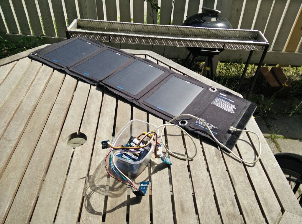
oRx_suys2V2JUYJhLQthLLqJq70bgz4CHFJbJFX7Y91ITrO0sIAfTT5BQuICCTimOx9RmnlIXvmY=s2048Testing the luminance sensor and Arduino with solar panels.
Backend server

Backend server was implemented using NodeJS, MongoDB and Express and was hosted on Heroku. Backend loosely follows REST architecture and returns all the data as JSON objects. Most of the data is served straight from the database except for a few aggregations for the latest and average values.

The implementation uses Express for basic routing with generic code modules to allow easy extendability. Authentication is not yet supported, but basic skeleton for authentication middleware is present in the code. Currently the application is insecure when used in an open environment such as Heroku.

Data visualization

We visualized the data with Angular.js using Bootstrap and angular-chart.js libraries. The dashboard is responsive and reactive, so it fits on every device and time series information is constantly updated.

Basic information displayed is temperature, humidity, amount of light and if water needs to be added to the tank.


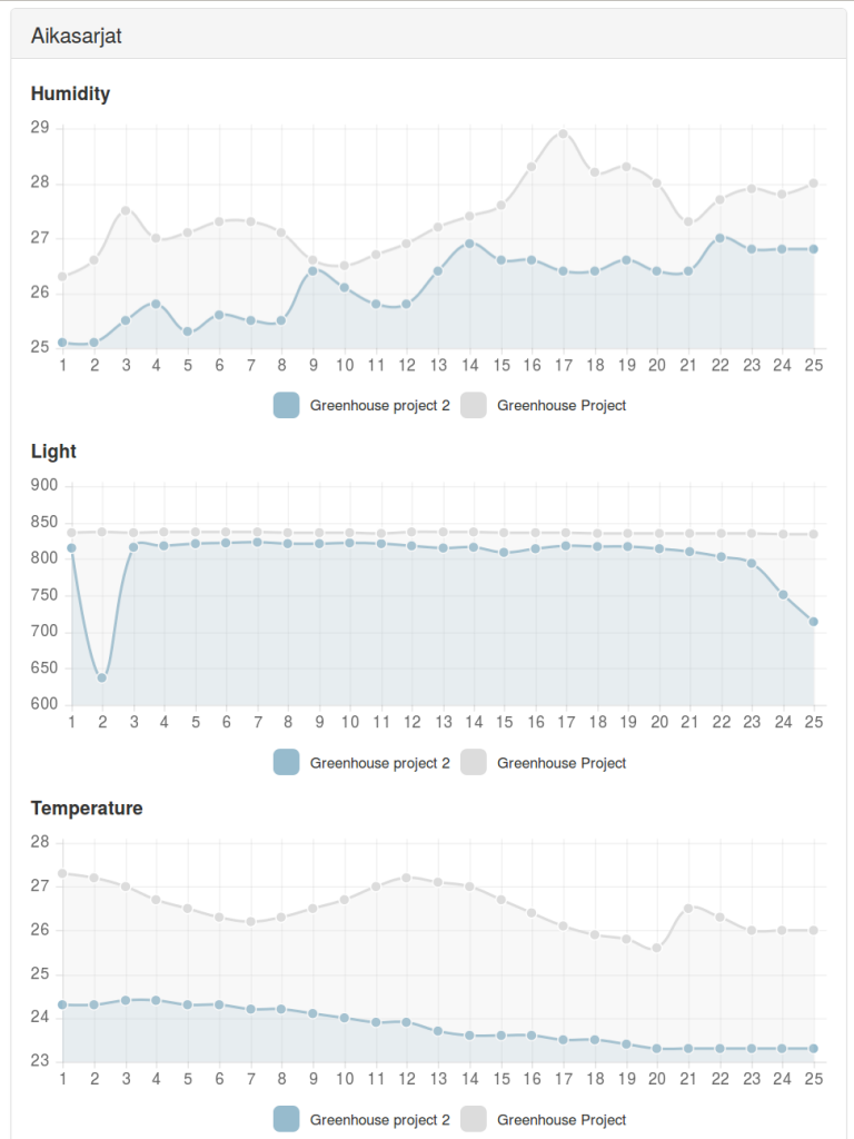
iot-frontTime series charts displaying real data (Greenhouse project 2) and dummy data (for testing purpose).
Additionally, historic information on temperature, humidity and light levels is shown in time series charts.

Reactivity is accomplished by retrieving the data from the backend service in 10-second intervals and updating the time series charts accordingly allowing the user to see changes in real-time.

This front-end lives in its own Heroku instance and is supported by a static NodeJS file server. Information is retrieved from the backend service with basic HTTP GET requests using Angular.js $http provider.

3D printing the parts

We designed a hydroponics system which consists of a water tank including a pump and plant modules connected to the tank. Plant modules are simple cubic boxes that can be lined up to make the system extendable. Inside each module, a removable holder supports the plant leaving only its roots in contact with water.

We used TinkerCAD to create the STL models of the parts. Printing was done by Makerbot Replicator 2, which used polylactic acid (PLA) as feedstock material. PLA is a biodegradable derivative of corn starch.

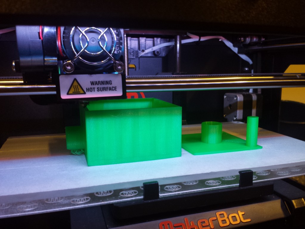
First we printed a plant module using standard quality and 15% fill density (amount of infill in,  for example, walls). It took 4.5 hours to finish, so for the next module we used low quality and 10% fill density. This reduced the printing time to 2.5 hours. The printer had to be watched during the printing because sometimes PLA filament fed to the machine got tangled and snapped, terminating the process.

20150518_163517Printing the first plant module. First version of the plant holder on the right side.

We made multiple versions of the holders and some other small parts. This was where 3D printer became handy: it was easy to see which designs worked and which did not after having the actual physical object in hand.

Testing the system

After having all the parts printed we hooked two plant modules and a tank together, put the pump and a hose in place, added some water and started the pump to see if the system actually worked. Water flowed easily through all plant modules back to the tank but after a few minutes we noticed that some part of the system was leaking. We tried to seal the joints between plant modules by adding some silicone and glueing the modules together. It didn’t resolve the leaking issue as it seemed that water was leaking through the bottoms of the plant modules. Next we covered the interiors of the plant modules with water resistant paint but it didn’t help either.

We are not sure if the plant modules could have been made waterproof by printing them with higher fill density. However, leaking was not really a major issue since the containers kept the water long enough to demonstrate how the system works. Below is a video of the final version in operation. Arduino was placed in a wooden box to make sure it did not get wet. Luminance and temperature & humidity sensors are on top of the wooden box. The plant module with a plant in it is filled with LECA.

https://youtu.be/reLooi1AvpA

Source code for the project is available on a Github repository: https://github.com/hzhulkko/iot

The team
Heidi – Arduino programming, hardware testing, 3D design and printing operations
Jarkko – Backend server, 3D design
Lari – Data visualization, 3D design and printing operations

Visualizing metrics from greenhouse on an online dashboard

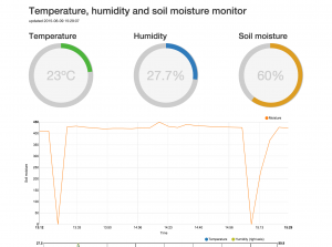
In this brief blog post we explain how we built a small system that monitors the temperature, air humidity and soil moisture of a small greenhouse or a plant pot. The prototype was implemented as a 2-man team with Mika Aho and Jyri Lehvä. The focus of the project was more on the software than on the hardware and the goal was to get to know the very basics of Arduino environment and learn something new about web programming in general.

The idea of the system was as simple as providing information about the environment of a small greenhouse to the gardener. We felt that monitoring the temperature, air humidity and soil moisture were the most important metrics we should be able to provide. To achieve that, we selected two sensors. One for the soil moisture and the second one to monitor the temperature and air humidity. The metrics from the sensors were saved to an online database and presented by a web application as graphs and charts so that the gardener can browse them with any modern web browser.

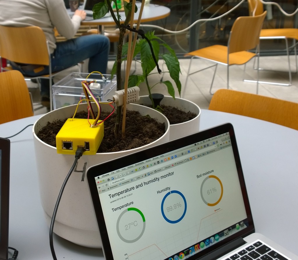
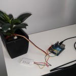
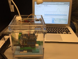
Prototype in action

Prototype in action


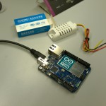
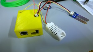
Arduino Yun and the sensors

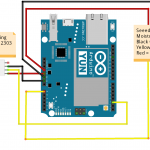
The hardware used consisted of Arduino Yun and two sensors; AM2302 for temperature and air humidity and a Seeedstudio Grove sensor for soil moisture. We chose Arduino Yun because it felt like an easy device to use; it runs a Linux and contains a Wi-Fi chip. All we had to do was to setup it, plug it to a laptop with Arduino IDE and connect the sensors. After that we could just start writing code. Very Easy!

For the Arduino Yun we wrote a simple program that reads the input from the sensors attached to it every 10 minutes. The input from the sensors is then formatted to JSON and pushed to Firebase which is a web service for storing and querying data. The delay between reads from the sensors can be configured to any value that fits the best.

The Web application

The web application was built using Nodejs, ExpressJS and Firebase as the backend. The frontend was built using AngularJS, Angularfire and using D3js to draw the charts. The code can be found from Github (https://github.com/jlehvae/exgreen2k15). The application was deployed to Heroku (https://guarded-mesa-9835.herokuapp.com/).

The most significant challenge of the web application was to correctly visualize the data. For visualization we used Angular directive called Angular-nvD3. The Angular-nvD3 didn’t have very specific instructions on how to format your data so that it is correctly visualized and that’s why we had to take a trial and error approach. Configuring the charts correctly and formatting the data properly can take a while if you don’t have any previous experience with D3js. After we figured out the correct way to input the data, we were getting charts that didn’t look quite right. Soon we found out that we were actually missing a specific CSS file. After adding the missing file everything pretty much started working.

Online Dashboard at Heroku

Online Dashboard at Heroku

3D printing

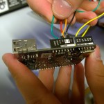
The final step was 3D printing a case for our Arduino. We had no experience working with a 3D printer before. It was surprising how easy it was to print the case. It turned out the Internet is full of readymade 3D models for different things. It took only a couple of minutes to search for a model that is designed for Arduino Yun. Only problem with the model was that we had two wires that needed holes on top of it so we could have the sensors attached while the Yun is in the case. We made the holes using Tinkercad (https://www.tinkercad.com/). It’s a website that let’s you import and edit 3D models using a web UI and export them back once they are modified.

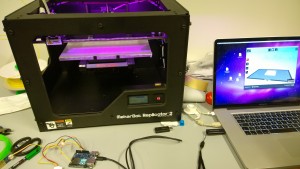
We used Makerbot Replicator 2 as the 3D printer. It was easy to use; just add the file of the model you want to print using the MakerWare and press start (we pretty much used the default values for everything). Printing the case took around 2 hours in total. The top and the bottom part of the case had to be printed separately so the case wouldn’t break apart during printing as there would have been nothing to support the roof of the case. The top part of the case was printed upside down so the roof was supported facing against the floor of the printer.

Sensors and the validity of the data

There were some problems with the moisture sensor as the readings before and after watering a plant were not that different. The plant in question was supposed to be quite dry yet the sensor gave readings of 400 ish (according to Seeedstudio this means that the soil is moist) and after excessive watering the readings only went up by around 40. The fact that our sensor had been used before and appeared quite worn probably had something to do with this.

The setup was tested on multiple occasions by simply turning the device on and manipulating the sensors by

  • touching the moisture sensor
  • putting the moisture sensor in soil and pouring water into it
  • blowing into the humidity/temperature sensor
  • leaving the temp/hum sensor under direct sunshine

What we found out was exactly what you’d expect: the sensors (and thus our charts) correctly reacted to changes in the environment. This didn’t really mean that the data was valid, though. If we had one or two more copies of the sensors we could have tested if they are all giving out same metrics in the same conditions. Now there was no way of knowing if the sensors were accurate or if the data was valid or not.

Continue reading

Internet of Things: Greenhouse Environment Station

By: Ivan Atarah, Rupsha Bagchi and Yan He

We wanted to have a log of the weather in the greenhouse in our Exactum building, with PC logging and graphs. So we made a device which measures the real-time environment variable from multiple sensors in the greenhouse, from where the results can be easily checked and understood.

The arduino UNO board receives the information from the sensors and pushes them to a database on the cloud with the help of the adafruit CC3000 wifi shield.  The data stream on the SparkFun database is then analysed and prepared as graphs using the Analog.io APIs.

This system can be used to monitor, for instance, how much sunlight a specific type of plant is getting. So basically we can use the information from the data to analyse whether the environment is conducive or detrimental to the growth of specific kinds of plants.

The source code of our project can be found here. And here is the link to our SparkFun database. Also, this is where you can see our desktop application with the graphical view of the data (on analog.io).

Components

Arduino Uno and charger
Grove-Base Shield V1.3
Adafruit CC3000 WiFi Shield
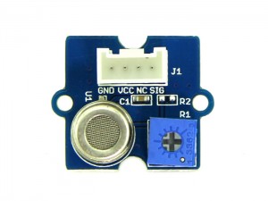
Grove-Digital Light Sensor
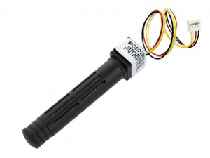
DHT22 Temperature-Humidity Sensor

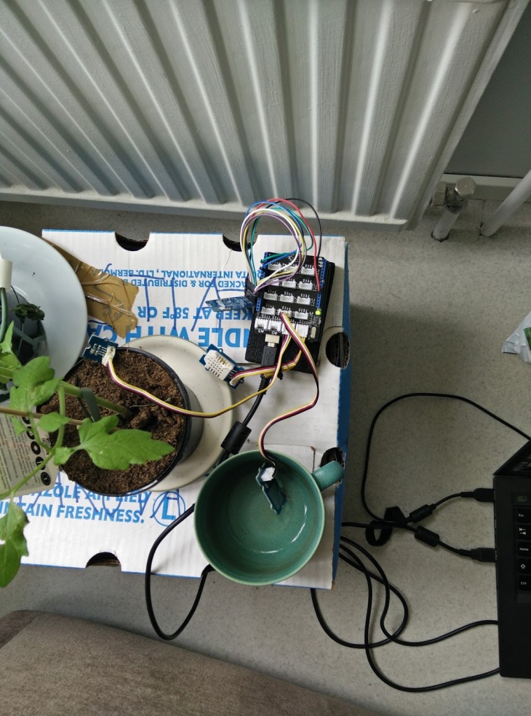
11355382_987784461240318_444653769_n

The system and its output

11263826_986476921371072_333993720_n

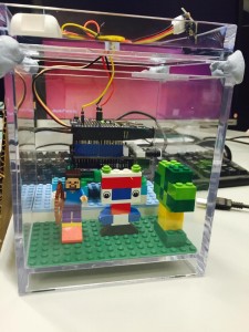
The front view with the added lego accessories

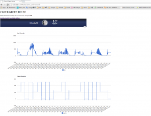
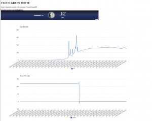
data

how the data is stored in SparkFun database

graph

The graphical view from analog.io


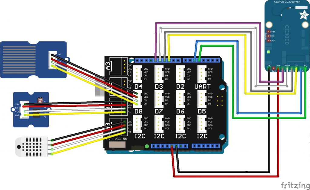
weather-station-fritzing-breadboard

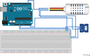
The wiring diagram


P.S. We haven’t shown Grove-Base Shield and Adafruit CC3000 WiFi Shield in the wiring diagram, due to some fritzing library issues.

Difficulties encountered

  • Adafruit CC3000 Breakout WiFi chip was faulty: We discovered it after repeatedly trying to connect to the network and failing. We had it replaced with adafruit CC3000 WiFi Shield.
  • Connecting to firebase: We tried multiple ways to send data to firebase for many days, but kept getting stuck at some point. We switched to Thingspeak and eventually to Sparkfun due to its very easy-to-integrate api.
  • We found a perfect Arduino case to 3D print on Thingiverse but could not resize the parts separately on Tinkercad, so we left a comment to the designer. The author was answered very quickly and the communication was a success, even though the model could not unfortunately be changed. So we switched to another 3D Lego mount for Arduino, here is the link.

Future Enhancements

We has originally planned to include other sensors namely carbon dioxide sensors to measure the changes in CO2 concentration around plants, toxic gas sensors and air pressure sensor to predict when it might rain. Along with that, we also wanted to be able to predict the greenhouse environment based on incremental history from our data, with the help of machine learning algorithms. We could not the due to the time constraints.

Grove_CO2_Sensor

CO2 Sensor

HCHO_Sensor_01

HCHO (formaldehyde) Sensor

Grove - Barometer Sensor

Barometer Sensor

We think being able to see the data and control the system from out smartphone is also a good idea. So we currently working with the data we have to make a mobile application.

Learnings

We had hardly any previous knowledge of hardware based projects. We took a while to pick up things from scratch, making our way through learning, debugging and testing the hardware issues. The hardest part of the project was probably writing the code to send a POST HTTP request to the database and figuring out how the various arduino libraries exactly worked. The greenhouse exactum course tutors were of great help to us, and the course gave us the motivation and the confidence to develop more arduino based projects.

Internet of Things: Auto Ventilation System

Imtiaj Ahmed & Oswald Barral

How much do you care of your plants? Do you know whether your plants in the greenhouse are boiling, freezing, or inhaling properly? Who is taking care of your plants while you are away enjoying the summer in your “loma mökki”? Your plants might be praying that someone opens the greenhouse window, but you can’t hear their voice, you can’t understand their language. One solution might be to hire a plant-human translator, so that he can translate their language for you, understand their claims, and open or close the door or window of the greenhouse accordingly. This solution might sound quite reasonable to you, but we believe that our proposed alternative will make you think otherwise, as you will never have to worry again for the wellbeing of your plants.

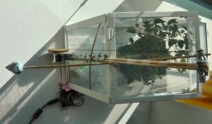
Side view of the system and mini greenhouse.

Side view of the system and mini greenhouse.

Arduino, adafruit cc3000, and dht22 sensor. Count also the beautiful butterfly.

Arduino, adafruit cc3000, and dht22 sensor. Count also the beautiful butterfly.

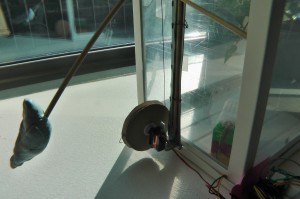
Circular lever (using paper) and a bird as a counter weight (using blu tack reusable putty)

Circular lever (using paper) and a bird as a counter weight (using blu tack reusable putty)

Top view of an artistic hand work.

Top view of an artistic hand work.

Materials

We built a greenhouse Auto Ventilation System. In order to prototype our system, we used a mini greenhouse made of transparent glass. An Arduino UNO microcontroller was used to control the system. A wired dht22 sensor  (Adafruit AM2302 wired, http://www.adafruit.com/products/393) was used to sense the temperature and humidity of the greenhouse, and a servo motor was used to open or close the window of the greenhouse according to the signals from the microcontroller. Additionally, an adafruit cc3000 wifi breakout board was used to connect to the internet in order to feed on-line the sensor readings to to a data server.

Wiring and Code Library

We followed the wiring and source code library of adfruit cc3000 from https://learn.adafruit.com/adafruit-cc3000-wifi , dht22 sensor from http://www.adafruit.com/products/393  (another source, http://playground.arduino.cc/Main/DHTLib  ) and Servo motor from http://www.arduino.cc/en/Reference/Servo. The following figure shows the complete wiring.

Wiring diagram.

Wiring diagram.

Control Logic

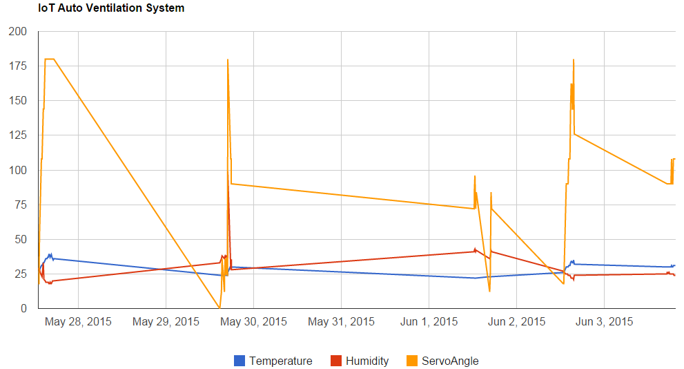
Arduino UNO reads the temperature and humidity data from the Adafruit AM2302 (wired DHT22) sensor every ten minutes, controlling the opening or closing of the greenhouse window through the rotation of the servo motor. The rotation of the servo motor rotation angle (0º – 180º) is mapped to the temperature (20ºC – 30ºC) and to the humidity (25% – 50%). Arduino UNO sends the temperature, humidity and servo motor angle data to a data server through the Adafruit CC3000 WiFi module. Data in the server is logged together with the corresponding timestamps. Additionally, an automatic plot is generated to facilitate the interpretation of the sensor data over longer periods of time.

Data cloud

Following the easy tutorial from sparkfun (https://learn.sparkfun.com/tutorials/pushing-data-to-datasparkfuncom/all) we pushed the data to the sparkfun’s cloud data server https://data.sparkfun.com.  You can see data from our system at https://data.sparkfun.com/iot_uh_ia_os.

Sample Readings.

Sample Readings.

Next comes the visualization. We followed the tutorial and sample source code from http://phant.io/graphing/google/2014/07/07/graphing-data/  of using google chart to draw the live chart from the data cloud. To draw chart we used data only from first page of the data server. You can see the live chart at http://www.cs.helsinki.fi/u/iahmed/iot_graph.html .

Sample Chart.

Sample Chart.

Source Code

The complete source code can be downloaded from here in Github, https://github.com/ImtiajAhmed/IoT_AutoVentilationSystem

Problems

Problem-1

After a pilot test of 2 days we figured out that the cc3000 wifi module was getting stuck after a couple of attempts to connect to the server, if the gateway or server were not responding. We then started to surf on the internet and forums to find a solution to the problem, but we could not find any suitable solution. The best way we found to solve the issue was to restart the system when it was getting stuck. In order to do that, we connected the reset pin with the digital input pin 7 using a wire, and added some chunks of code where necessary that sent a low pulse to the reset pin, via the digital input pin 7. With thefixed issue, we tested the system for about a week. We realised that our system was working fine, but the data.sparkfun.com server most of the time causes “504 Gateway time out error”. In the future, we are planning to change the data server with a more robust one.

Problem-2

We used Serial. print command to get some feedback from the Arduino to know what it is doing, for debug purposes. It works fine when we plug the Arduino into the PC, but stop working after a while if we run the system without connecting to the PC or any other serial receiver. Then we figure out that the Serial.print command blocks the system because the output buffer of the serial transmitter is getting full.

We went through the source code of the Arduino library, and found in HardwarSerial.cpp, there is a code line that blocks the system until the transmitter’s ring buffer gets a free space.

while (i == _tx_buffer->tail);

We changed this with the following:
int tmpCounter = 0;
while (i == _tx_buffer->tail) {
    tmpCounter++;
    if(tmpCounter>200)  //wait for a while; give a chance to the serial device to receive data, if                                                  //connected.
        return 0;
}


Now it’s working fine.

Learnings:

It is always fun to work with arduino and physical devices and hardware. It forces you to take into account all the different components involved in the designing and implementation in the early stages of a system, taking care of the electronic circuits, controlling logic, power, filter, resistances, wiring and soldering, and so on. The Internet of Things course helped us to re-learn those. Additionally, the course made us leave our comfort zone, and think out of the box, as we faced multiple software, hardware and even physical (such as when building the mechanism to control the window) challenges. The best part is that we really enjoyed solving them, especially the latter ones!

Exact Greenhouse

Since year 2010 the rooftop of Department of Computer Science has been a busy workaround for scientific experiments at the University of Helsinki.  The location was first used for studying whether it was possible to cool computer servers with the hash Finnish winter air.

Turned out that it was.

pervila

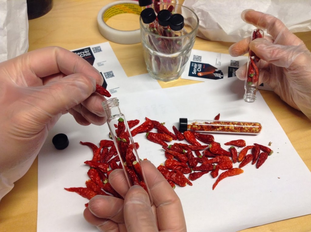
Dr. Mikko Pervilä (DBLP) continued his experiments by building a low-cost greenhouse to accompany his icy server rack. And flocking came the academic chili farmers.

He’s the one in yellow overalls.  Yes we have snow in Finland.

tube

After two years of hot research topics and hefty harvests Dr. Pervilä dismantled the final server from his rack and ended his work at our Department. Future of the research laboratory was left open.


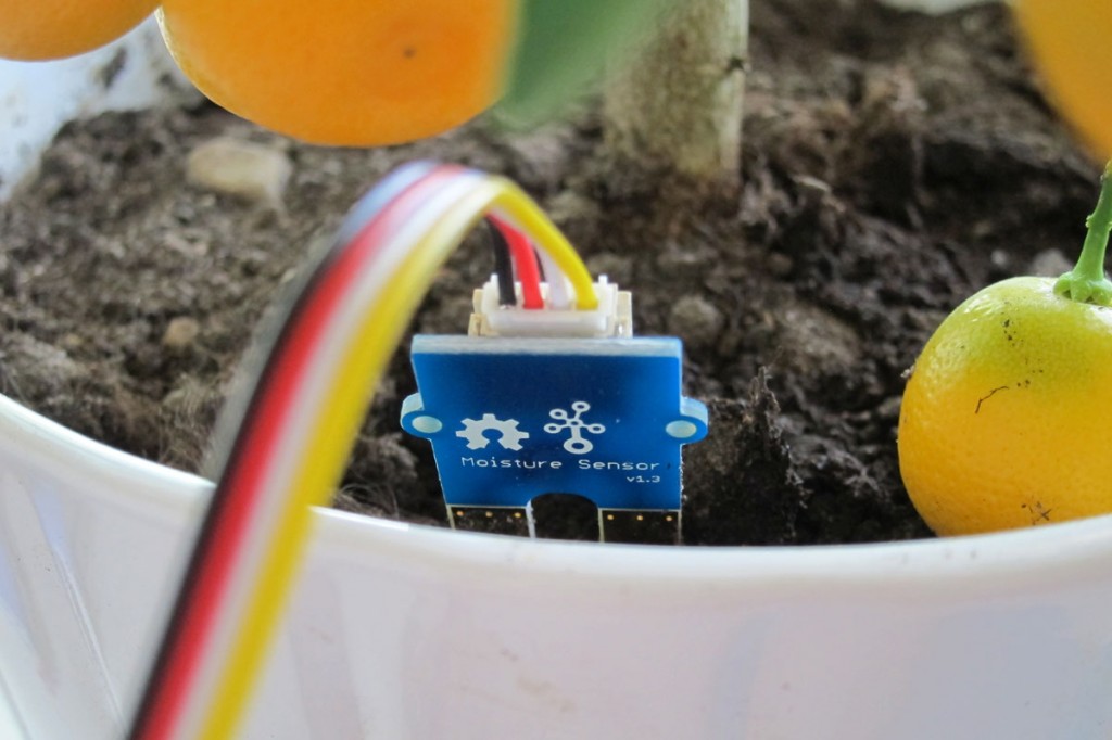
Current prototype uses Grove moisture sensor.


That’s when we took over

On May 2014 we launched opportunity to study what may become the next big thing after the invention of WWW.  Our fresh and green  IOT course  was and will be held in 2015 at the urban rooftop gardening spot with enthusiastic  group of Computer Sciencentists.

This blog tells the small story of the courses arranged 2015-2016, where participants created prototypes for systems for helping the chili growers to work together.

Yours truly,
Hanna Mäenpää
Samu Varjonen
Arto Vihavainen

We’re on Twitter

HEY! PS!

katto

Fifth Dimension  has an ongoing research at the location. They study how green roofs can help urban environments and energy efficiency. Isn’t that awesome? 

BonsaiBox

Inspired by Fatalii, I decided to cut down one of my Bolivian Rainbow chili plant which I had kept alive throughout the winter 2013-2014. A chili which has a lot of leaves dehydrates quite a lot of water and therefore placing it into an ordinary bonsai planter just does not appeal to me. I was afraid that the small container did not hold enough humidity and the plant would suffer from recurring droughts, which are exceptionally bad for chilis. Yes they are.

rainbow

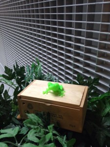
So, the idea of the BonsaiBox with an Arduino Uno followed. I stole an empty tea box from the Department’s coffee room and drilled some holes to it’s back and front panel. I ordered an Adafruit CC3300 Wifi breakout board and while waiting for it to arrive,  printed both a 9v battery holder and a light mount for the Uno to make the installment stable within the box.  And a cute green frog to sit on top.

 bonsailaatikko

I used a “Grove” soil moisture sensor from SeedStudio. Finding the right ranges for different soil states took a couple of days and tries. Resolution of the sensor was with 5v+ from 300…950, which was quite ok for this purpose.  I ended up with three levels:

“I’m OK”
“soil is just a little dry” and
“pour me water or I’ll die”

This is the soil moisture sensor:  It is fit for only 5cm long so it was ok for my purpose with a very small container. The sensor wouldn’t be feasible for bigger ones

I experimented with  RGB leds. I had a common anode lying around. It was fairly confusing to figure what should be given as an input for it. I went  to Partco and bought a cathode and  BOOM, code made simple. I also had a simple photoresistor with a LilyPad buzzer and switch left from my previous projects. I used these parts to enable interaction with a person sitting next to the Bonsaibox. The buzzer really sounds like a frog.


Getting online
Wifi shield arrived, I almost killed it with my bad soldering. But finally, got the parts assembled and started integrating my code from the output experiments with example code of the CC3300 breakout. It worked.

Pseudocode: 

Measure humidity
Send sensor value to Janne’s backend

IF
soil is is humid
    blink blue with RGB LED

ELSE IF
soil is drying out
   blink yellow with RGB LED

ELSE IF
soil is completely dry
blink red with RGB LED
if it has been dry for the whole day
start making a frog-like sound continuously until the plant is
watered.  Play it even louder during the night. Yes, that’s a bit
mean but that’s the way I like it.

ELSE
wait for a while and measure the humidity again.

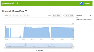
The data really nice in Janne’s EGH-chart. Thank you for the awesome work, man.

bonsaibox_chart

Learnings:

My prior knowledge on microcontrollers was limited to one successful and one failed project with Lilypad (I couldn’t figure anything meaningful to do so I trashed the whole project). I did know how to code but hadn’t done it in years.

So the outcome: inside the Bonsaibox.. Oh it’s ugly. Looks like a homemade bomb. I didn’t order a sensor shield  which was a bad mistake. I had to take apart all the nice plug&play connectors and solder a lot.  After getting the hardware together it was really hard to keep the wires attached. People. Don’t save from the wrong place. Get a shield.

Programming was fun. There were ready libraries for the WiFi and it was easy to integrate them with my code. I got a lot of confidence as a coder from this project.I learned to Google from the right places.  I CAN! And I will do it again.

Internet of Things: Hydroponics!

The goal of my project on this Internet of things -course is to design and implement an environmental condition monitoring system for hydroponics. In a hydroponic system plants are grown in a nutrient solution without use of soil.

I’ll be working with a platform called Arduino, which is a single board microcontroller and an open source development platform. It provides a way to create devices which interact with the environment, with sensors, for an example.

The sensors I’ll be using are based on the Grove system manufactured by Seeedstudio. Its main part is the base shield, which is plugged into the microcontroller. All the sensors are attached to this shield. I plan to include sensors for temperature and humidity of air, ultraviolet intensity, air quality and water temperature. Initial plans were to also measure the pH and electric conductivity of the water, but this part seems a bit problematic at the moment.

My system will measure the data points and push them to the web server using HTTP GET. That’s why I plan to use the Arduino Yún board, which has built-in Ethernet and WiFi support. The user interface will visualize the data stream by drawing real time charts of it.

Sounds like fun, doesn’t it? 🙂

UPDATE: My source code is now online on GitHub!

I have proceeded as planned and used an Arduino Yún board with the Grove sensors. The sensors include a temperature and humidity sensor (DHT22), an ultraviolet light sensor (GUVA-S12D), an air quality sensor (TP-401A) and a 1-Wire temperature sensor (DS18B20), which is used for monitoring the water temperature. These are all connected to the Grove base shield, which in turn is connected to Yún, to avoid any unnecessary tinkering.

The code for the Arduino includes an instance of a HTTP client, which uses GET to send different data values to the Exactum Greenhouse web page. The sensor values are read using corresponding libraries, which are also available on GitHub. The hardest part for me in this project must have been understanding these libraries and how they function.

I learned a lot about Arduino and using different sensors on this course, and I plan to continue developing using this platform. My knowledge of electronics in general has also improved significantly. I will also continue working on my hydroponics system in the autumn. Plans are to hack a commercial product by integrating my system seamlessly with it, but we’ll see what happens in the future. 😉

Internet of Things: Think Visual

My target for this course is to create a system where it is possible to track measurements from multiple sensors in real-time, and to do this in a scalable way. What I mean by scalable is that it should be possible to add at least dozens of sensors to the network, and the results should be easily monitored and understood. The emphasis is thus not so much on the code that is written for the devices, such as arduino, but more on the whole architecture. The code in individual arduino board should not be dependent of the way the results are shown for the end-user, only a URI where the data is sent is needed.

The system is push-based in the sense that data is pushed from the sensors to a database, from which it can be processed or used as wanted. Here, a Firebase database is used to be able to update a web-client immediately when a new reading is received. Otherwise the web-client would have to poll for new values.

The results

I created a web application where users can registrate and login and create their own channels for receiving and showing data. Each channel has its own chart-view and can have multiple time-series’ of data. Chart-view was chosen so that historical changes can be easily noticed from the view. The data in each series in a channel updates in real-time, so that data that is send from a remote device immediately shows in the chart without polling for server or doing a page load.

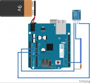
The arduino part that I made consists of an Arduino duemiliano board, an Ethernet-shield and a DHT11-sensor. DHT11-sensor can measure temperature and humidity, which were used to calculate also the dew point. All the three values are sent to a proxy-server (because Firebase can only handle SLL-connections, which is a bit too much for arduino), which sends them to Firebase. The web-application has a connection to the user’s Firebase-channel and updates the chart.

A great majority of my time went to building the web-app. The arduino code was pretty trivial, as I only needed to be able to send data out and not do any processing on incoming data. All in all, I am very happy of the result, and will probably continue to develop the web-client.

egh_bb

Schema of the arduino board, Ethernet shield and DHT11 sensor


screenshot

Example view of the app with three series in one channel


Automatic Air Flow Regulation System for Exactum Greenhouse

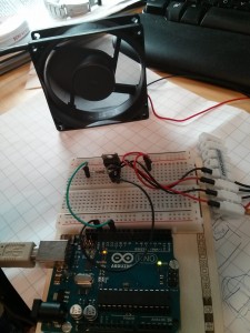
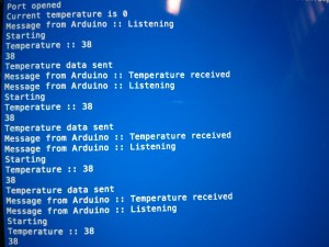
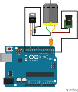
The greenhouse is a glass container with very little openings. In summer when it is really hot inside, we need to blow cold air. A fan would be the best possible tool for that purpose. Nobody really has time to switch the fan on and off time to time, in the morning and at night, at sudden rise or fall of temperature. Therefore it is required to have a fan that switches on /off and also regulates automatically. Thanks to the Magical Flower Pot that already has a DS18B20 1-Wire temperature sensor which sends temperature readings to our Firebase database at regular intervals. I am reading those values after ten seconds and sending the temperature to Arduino, which controls the fan. When the temperature is below 20 degree centigrade the fan stays off. Above 20 degree centigrade it switches on and regulates upto three levels up.

The idea is to install two fans on two opposite side walls of the greenhouse so that air can flow properly. We will connect two fans with the same circuit. There will be a computer with the system which will run the Node Js code to fetch json data from Firebase and send to Arduino.

Components

  • 12+ V DC Fan
  • TIP 122 NPN Transistor (Datasheet)
  • Arduino UNO
  • USB Connector
  • Breadboard
  • Transistor, Capacitor (According to requirements)

Diagrams

Circuit Running FanCommunicationCircuit_diagram


Code

The code written for this is at

https://github.com/sayantanhore/Airflow-Regulator.git

Node js and npm package “serialport” is needed to run this code.

Problems Faced

I had a serious problem regarding communication from Arduino and Node Js frontend. The messages coming from Arduino appeared to be improper and I (with Samu) found out that the transfer is so fast that two subsequent messages were always colliding and spoiling both of them. We introduced a small delay from Arduino and that solved the problem.

Second thing is initially I made an incorrect circuit and “SUCCESSFULLY” fused the power source.

Conclusion

It was a great learning experience and I am looking forward for mode IOT courses in near future. THANK YOU ALL.