Author Archives: Deleted User

About Deleted User

Special user account.

Welcome to the green lab!


We arranged seven week “Exact Greenhouse” courses at the Department of Computer Science of the University of Helsinki between 2014 and 2016. This course attracted a total of 47 students with different skill sets which were interested in building a greenhouse that was maintained by microcontroller-based devices. There were no other requirements for attendance except for that students should have completed a BSc degree in any of the specialisation lines of computer sciences. This requirement was set because participants would benefit from knowledge that typically develop during their BSc thesis work.

Greenhouse technology was chosen as the topic for the abundance of creative ideas and tutorials that could be found online. As industrial systems for agricultural automation have existed for decades, a wide range of small scale consumer goods were available. Many of them integrated mobile interfaces and social aspects into gardening, providing rich inspiration for innovative product design. As for the numerous online tutorials for do-it-yourself prototyping, evaluation of possible technical architectures was easy already at a very early stage. 
A Facebook course page was established and inspiring ideas with instructions for completing first milestones were communicated through it. For those students that did not use Facebook, the same information was delivered through email. This blog post summarises learning outcomes of the courses throughout the three years.

You can find the story of the research lab facility here.
The first course in 2014 attracted 12 students.
Course page.

Problem Solution Microcontroller Members
Maintainers want to view the status of the facility to decide which maintenance tasks are required in the future. A web service that provides a graph visualization for any IoT device that is configured to push data through its general purpose API. Arduino Duemillanove 1
A maintainer needs to be alarmed if plants dry up. A product concept for a smart flowerpot container with a water reserve. Electric Imp 2
Humidity sensor unit to be placed in soil. The system alarms maintainers by creating a sound, helping to locate the plant when visiting the greenhouse. Arduino Uno 1
The greenhouse gets too hot and humid during the afternoons. If doors are left open, it will get too cold during the night. A six point temperature and humidity sensor system Intel Galileo 1
An automated fan system, using data from the previous project Intel Galileo 1
Hydroponic cultivation is failing constantly for an unknown reason. A device that measures a wide range of environmental variables from air and water. Arduino Yun 1
Greenhouse maintenance team wants to know who has visited the greenhouse recently. A NFC keychain system to track visitors. Raspberry Pi 1


23 students enrolled to the second course in 2015.
Here are their projects:

Problem Solution Microcontroller Members
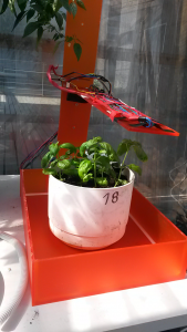
Plants grow unevenly as sunlight enters the greenhouse from one direction only A light-sensitive, rotating platform. Arduino Yun 2
Greenhouse maintainers may not be available at all times. Automated growing system that adjusts flow of water from a large tank and sends pictures and state information on Twitter. Raspberry Pi 2
Plants need different kinds of light for efficient growth. Sapling container with adjustable lightning. Raspberry Pi 3
Different plants consume water at different pace. A set of independent sensor modules for one microcontroller unit. Arduino Pro Mini 2
As the amount of plants increase or decrease, several maintenance tasks are needed. Hydroponic growing platform that can be easily extended as the farm grows. Arduino Uno 3
Maintainers want to overview the status of the facility to evaluate which maintenance tasks are required. A multifaceted web service providing a graphical visualization. Arduino Yun 2
Temperature of the greenhouse gets very high in the afternoon. If the air is moist, soil and plants may develop mold. Automatically functioning pulley system that adjusts ventilation according to temperature and humidity. Arduino Yun 2
N/A Device measures air temperature, humidity, CO2 Arduino Uno 3
Device measures soil temperature, humidity and light Arduino Uno 1


The last course in 2016 attracted 12 innovators.
Course page. 

Problem Solution &  link to the project page Microcontroller Members
The greenhouse attracts pigeons Automated movement sensing water gun to deter the pigeons. Raspberry Pi 1
Plants need different kinds of light and shade periods for efficient growth. Automated system to control built-in lights and shades Intel Edison 1
Maintainers need to be notified when soil dries. Maintainers want to reconfigure the device to match needs of different plants. Automated system to control built-in lights and shades Arduino Mega 2
Maintainers need to overview the state of the facility and be alarmed if a reaction is needed. Advanced web visualisation prototype Lightblue bean 1
A system that monitors temperature and humidity of soil. Image analysis tool for identifying changes in the look of the plants. Raspberry Pi 1


Publications

This article shows specifics of the hardware required to arrange a similar course and the first year’s course syllabus.

Blending Problem-and Project-Based Learning in Internet of Things Education: Case Greenhouse Maintenance.” Proceedings of the 46th ACM Technical Symposium on Computer Science Education. ACM, 2015.

This article summarises our learnings from teaching the three courses and offers key take-aways.
Assessing IoT projects in University Education – A framework for problem-based learning.” Conference: International Conference on Software Engineering (ICSE), Software Engineering Education and Training (SEET), 2017
Many thanks to the awesome research and teaching team.
Hanna Mäenpää, Samu Varjonen, Arto Hellas et al.
Greenhouse monitoring system

A monitoring system based on Light Blue Bean, node.js/Johnny-Five and d3.js

Overview

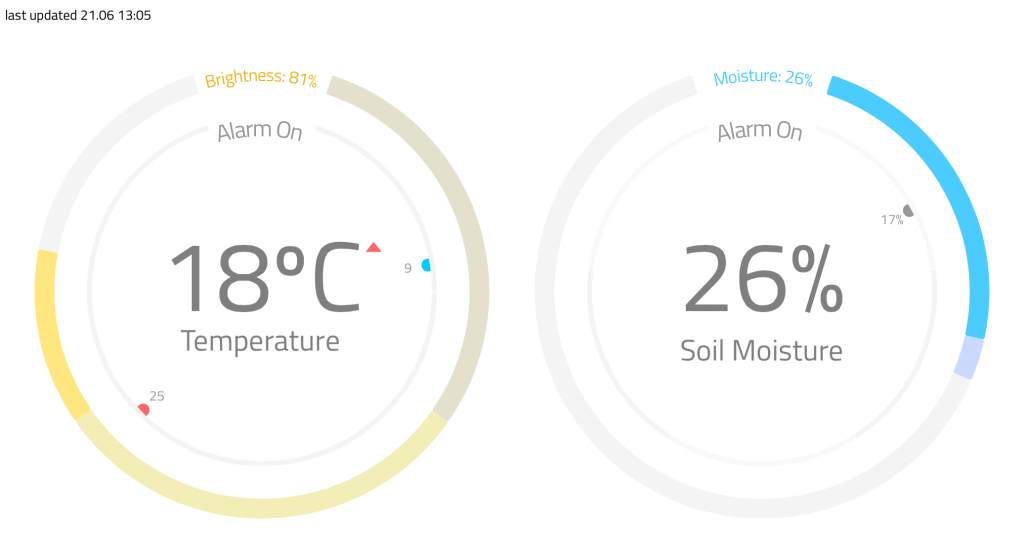
IoT is a huge trend nowadays but it doesn’t necessarily guarantee real value for users. This project is basically a simple system for monitoring plants well-being. Main focus was to present collected data in clear and readable format and offer real value (usefulness) to users. One design aspect was to offer user interaction instead of just presenting monitoring data.

  • Features of the system:
  • Current temperature
  • Temperature trend
  • Current light level
  • Current soil moisture value
  • Previous soil moisture value
  • Alarms:
    • Temperature – Adjustable low and high limit values
    • Soil Moisture – Adjustable low limit value
  • E-mail notifications based on user defined alarms and measurement data.

arc

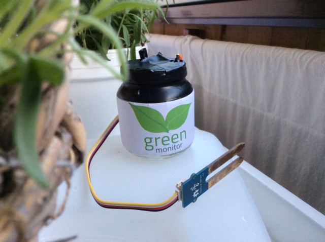
Light Blue Bean and sensors

Light Blue Bean is Arduino compatible micro controller board that uses Bluetooth Low Energy for communication. Bean has 5 digital pins and two analog pins that can be used also as digital pins. The Bean has also a built-in temperature sensor, a three-axis movement sensor and a RGB led.

Bean includes a small prototyping board where you can solder your sensors etc. I soldered photo resistor and wires for soil moisture sensor (basic conductor sensor). I soldered also external power supply wires for small battery back. Power source for Bean needs to between somewhere between 2.6v and 3.6v. Nominal voltage for Bean is 3.3v. I used old battery case with two 1.5v AA batteries which gave me around 3.2v when batteries were full. Bean was running several days with this setup.

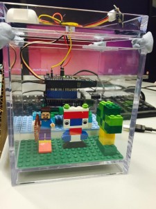
I installer the Bean into a small glass jar. One great advantage of the Light Blue Bean is it’s relatively small size and independence of wires (if you don’t need external sensors or power).

For starting to use the Bean you need first upload your program (sketch) to the Bean. First a sketch is loaded with Arduino IDE to the Bean Loader. Open Arduino IDE and Bean Loader programs.  Select Bean from the board list in Arduino IDE. Then you can upload sketches to the Bean Loader. After that In the Bean Loader app simply connect to your Bean and upload the program. You might need to update your Bean firmware also, depending on the version your device is running.

I found out that loading sketch (firmata-bean in my case) to the Bean was unreliable. Sometimes it succeeded and sometimes not. I didn’t do any serious testing but I started to think that bluetooth signal strength might have something to do with it.

IMG_0833

Back-end 

Johnny Five framework is a JavaScript framework for controlling micro controllers / bots. Johnny five works (almost) straight out the box with common Arduino boards and you can use also other boards with dedicated IO-classes.

Light Blue Bean is plain BLE connection device so you can’t connect it with usb wire. Fortunately there is an easy way to connect the Bean to the Johnny Five with Bean-io class.

Bean’s built-in sensors are independent from the Arduino side. For polling these sensors Ble-Bean is a convenient solution.

You need to include all these plug-ins to your Node.js script. It is also mandatory to load firmata-bean sketch to the Bean. After that it is pretty straight-forward to use the Bean with Johnny-five.

One thing that is needed to take into account when programming Arduino side of the Bean is different mapping of the pins, e.g. when using analog pins A0 and A1 you need to call pins 4 and 5.

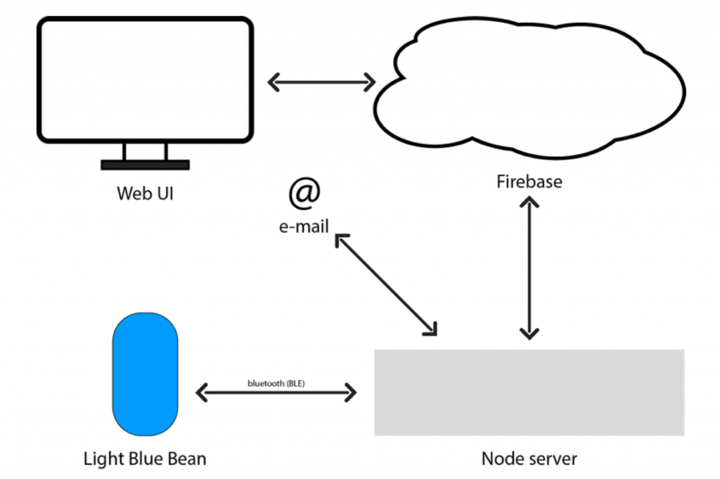
All the data was stored to Firebase. I used simple user account authentication. The data from the Bean was read and stored every two hours. When the Bean data is read script also checks if the values are within the user defined alarm limits stored in the Firebase. If the read sensor value isn’t within the user defined limits node script sends notification e-mail to the user with NodeMailer.

Sensor readings and scaling the values 

I used old soil moisture sensor which was already pretty heavily corroded. I needed to adjust the value range to suit the sensor readings which were approximately half of the theoretical maximum. I scaled the values before I stored the data to the Firebase.

Light level sensor was simple photo resistor that came with the Arduino Starter Kit. I needed to adjust the scaling of the sensor readings. The readings might be linear but I decided to cut the floor limit to around the 45% of the max value which was already very dim level.  This way the shown values were more in line with how humans perceive brightness. Probably plants needs also some light before anything happens.

Front-end

Front-end was made with D3.js and Angular.js. I first looked ready made re-usable charts, but I soon came to conclusion that I needed to do all the graphical presentations from the scratch with D3.js. If you want to use easily customisable charts with Angular for your data, check Angular-nvD3 or NVD3.js. I also included Ionic for easy platform conversations (iOS and Android). Ionic made it easy to run the app at certain IP so I could test the layout and usability with touchscreen devices such as iPad.

gh_view

D3 part is implemented as an angular directives. Angular controller and directives listens changes in Firebase and data is updated in real time. When user changes alarm seting angular code changes Firebase database values that are also monitored by back-end.

Detected problems / difficulties

I already mentioned that there was occasional problems when I was tried to load sketches to the Bean.

I also noticed that polling data from the Beans Arduino part didn’t work well when polling frequency was high. Average time the data updated reliable seemed to be around two minutes. If the polling time was below two minutes there were usually duplicated values from previous readings even the readings should have been something else. This problem didn’t concern the Beans built-in sensors controlled by Ble-Bean which worked just fine. There’s might be an easy fix for this problem but I didn’t found out the solution. Anyhow in my final version the data was read every two hours and the data seemed to be reliable with this frequency.

Future possibilites and reflections

The user adjustable threshold values could be used for new hardware implementations such as watering the plants or controlling ventilation / shading actions. Back-end (Node.js) could easily run in Raspberry or some other low cost device.

This project was clearly a prototype. The hardware installation could be done better. I thought about using 3.5mm jacks for the power and moisture sensor connection but I just didn’t buy those. However the glass jar worked well with the photo resistor. At code level there is also room for structural improvement but considering the scope of this course I’m pretty happy for the results as a whole.

Code examples can be found here.

The Pigeon Handler

From the land of the Angry Birds, now you can get a whole new level of entertainment by making those birds angry yourself!! If being the good guy of the story does not go with you then join the dark (and fun) part of the story.

IMG_0269

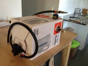
This prototype aims to scare unwanted pigeons on the rooftop of Kumpula Kampus. The main idea emerged from being wondering what I could do to help the plants from my family garden. Initially, I thought of a common problem we had in the front yard where it is common that random dogs goes to the garden and pee on the grass or plants we own. Thus, I thought that spraying water every time they come close might scare them and keep the garden safe from unwanted visitors. At the same time, I was searching for other ideas, one of them involved trapping small animals or taking pictures of them which sounded interesting but, not convincing enough. After a small talk and many jokes about the project, Samu Varjonen mentioned that trapping animals could be interesting since they have a problem with pigeons on the rooftop of the campus.

This talk lead to the creation of this fast summer project but, many small details were missing yet. Trapping pigeons might not be the best way to get rid of them, or at least it sounds like a heartless option, thus spraying water on them to scare them could be a potential option … as long as they do not start taking summer showers up there. I started to find projects that might be doing something similar. I found a project using Arduino and a motion detector to shots water at a random direction once the sensor detects movement. This project brought an important piece of information to this summer project, using a windshield water pump to not only spray water but aim to the target. You can see this project here.

Now with a more concrete idea and the previously mentioned project in mind, I wanted to extend it. Since I had no motion detectors at hand and I was in a hurry to start, I decided to use a camera which I was able to use not only for detecting motion but approximate the location of the target. Therefore, creating the final prototype for this summer project.

Prototyping

Requirements

The software and hardware required for the project includes:

  • Raspberry Pi 2 with Raspbian
  • A camera
  • OpenCV library for the camera
  • Windshield water pump
  • Servo motor
  • Diode
  • TIP122 Transistor
  • Two 1k Resistors
  • Power supply for the motor, in this case a small laptop charger (12v – 3 amp)

Extra (Not used but could be easily extended)

  • 2k resistor
  • Extra 1k resistor
  • URM37 ultrasonic sensor

Development

First, we have to install OpenCV on the Raspberry Pi. There are some tutorial available online in how to do it. The original library page is can be found here and one of the tutorials I considered really useful can be found here.

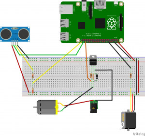
Second, we have to plug all the hardware. The following diagram contains 3 out of the 4 basic parts for creating this project. On the right side is the servo motor, which was directly plugged to the Raspberry Pi and contains only an input signal which modulates the direction. On the middle is located the control for the pump, in this project the power supply was a small laptop charger which Samu helped me to build. The left side, which is not included in the code of the project but I think that it can be easily extended is the sonic sensor, expected for avoiding shooting at far objectives and improve aiming accuracy. This feature was emulated here using the camera and will be explained in the following paragraphs. The fourth part is the camera but, in this case I plugged via USB and therefore it is not included in the diagram.

Greenhouse_bb

Once we have installed OpenCV, we can use the library for creating a motion detection system. In a nutshell, the system first have to chose a background image. In order to avoid problems with the first frames received and approximating the background image, the code read continuous frames in gray scale, smooth them using Gaussian blur and calculate the mean of squared error until a sequence has a similar value. This calibration only happens at the beginning of the program but, I think this should be calculated once in a while in order to adapt to small changes in the environment. Once it is calibrated, the system keeps reading frames and calculating the absolute difference. The difference can be used as motion detection since they are changes in the background but, in order to avoid noise and not significant changes, only the biggest change is taken into account and it has to go beyond an empirical threshold in order to be considered as movement. The movement is enclosed into a circle using the library and based on the location on the screen and the size of the circle we can approximate the position to aim for and a naive distance to the target.

The position of the servo with respect to the location of the movement in the frame is approximated using basic algebra. I measured the width of the camera vision at some given distance. Thus, we have a triangle with two known values which were used to calculate the angle of aperture. Hence, this angle can be given to the servo for aiming to our target.

In a similar fashion we can calculate the required duty cycle for each angle. For instance, we can easily obtain the values that give the rightmost and leftmost positions for the servo and then calculate the rest using those values.

Untitled

Finally, for the pump we only require to send a high signal to the GPIO in order to shot, and return it back to low after some given time. Therefore, completing the required code and completing the system.

The source code can be found here.

Eventualities

During the development I experienced some small eventualities that delayed the development and I would add here as warnings since some of them might be crucial. First, beware of the power supply you are using for the Raspberry Pi since it was the cause of many of my problems that showed as random errors or low performance in the best of the cases. Second, beware of the use and abuse of threads in the Raspberry Pi. Threads can increase performance in many cases but the Raspberry Pi has its limits thus, decide what would help the system if running on threads. In this project I only left the frame capturing part in a thread but only the capturing part since adding some calculations on the same thread stuck completely the system. Finally, while applying divide and conquer with the different tasks works great for developing and testing, keep in mind that the Raspberry Pi would have some problems once everything is running at the same time due to its limited power. This last eventuality made me rework half of the code in order to improve its performance.

Testing

Demo

Author

Angel Gallegos

RGB UV Smart Garden

green

The team:

Santeri, Miro and Joe

How did we end up doing this?

We all wanted some automated system to follow and manage our plants, even from another country. So we brainstormed some ideas, first we thought about automated watering, playing around with different setups of lights and water to find the optimal way of growing a certain plant. Then we narrowed it a little down, following the plants well being was enough, the watering part if wanted could be made with a pump of some sort.

And we all love of course a… plant disko!

howdidwe

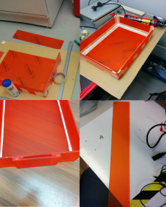
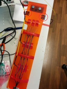
Plastic parts

First every piece of plastic was cut, then taped together and finally glued with silicon. Silicon that we used required 48 hours of cooling down.

plastic

Electronics & Code

Everything is controlled through Raspberry PI running Raspbian. Code can be found here.

The main idea of the project is to follow the light sensor (and maybe also temperature sensor) to control the 3 rows of LEDs in the ‘top part’.


The sensors

Sensors used:

  • A temperature sensor
  • A light sensor

sensors

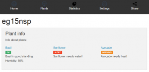
There are 2 sensors attached, light sensor and temperature as shown in the picture. The more important of them is the light sensor, which sends data to raspi from where the polled sensor data is sent to a cloud storage and from there to an SQL database through the filters. This data is displayed on the web UI.


The lights

Components used for this:

  • 9x Green leds
  • 9x Blue leds
  • 9x Red leds
  • 9x UV leds

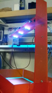
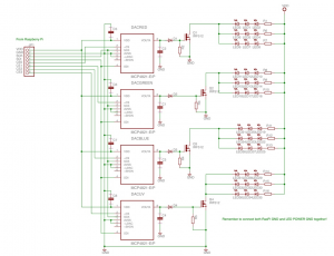
The leds are controlled through the Raspi. The raspberry PI is connected to a Digital To Analog converter where the voltage out is connected to a transistor. The lights are high intensity leds, so we used a external power supply (12V) for them, and for this reason we had to use mosfets between the leds and the raspi.

rgbu

ultraviolet

UI

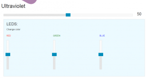
From the UI it is possible to control the lights, ex. if a plant needs more light in the evening you can turn the light level up with your phone.

UI

Backend

The backend was made with Node.js express. It had a simple API for sensor values and color control. Idea of the backend was to poll the SQL database running in cloud service, and to provide API for the UI for easy data handling.


The circuitry

circuitry

Finished Product

final

RIP list

  • one Rasperry PI
  • 2 DAC
  • 4 LED (2uv & 2 green)

Source code: https://github.com/Divinare/eg15nsp

Visualizing metrics from greenhouse on an online dashboard

In this brief blog post we explain how we built a small system that monitors the temperature, air humidity and soil moisture of a small greenhouse or a plant pot. The prototype was implemented as a 2-man team with Mika Aho and Jyri Lehvä. The focus of the project was more on the software than on the hardware and the goal was to get to know the very basics of Arduino environment and learn something new about web programming in general.

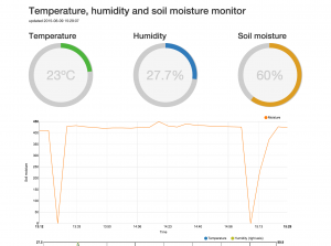
The idea of the system was as simple as providing information about the environment of a small greenhouse to the gardener. We felt that monitoring the temperature, air humidity and soil moisture were the most important metrics we should be able to provide. To achieve that, we selected two sensors. One for the soil moisture and the second one to monitor the temperature and air humidity. The metrics from the sensors were saved to an online database and presented by a web application as graphs and charts so that the gardener can browse them with any modern web browser.

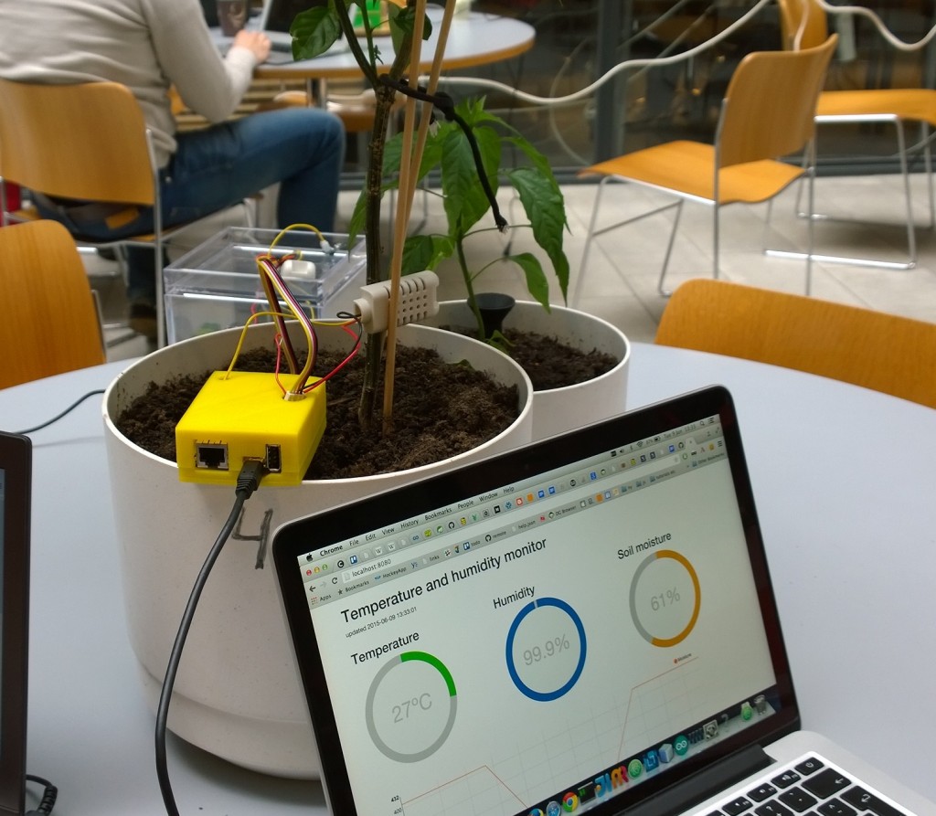
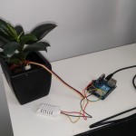
Prototype in action

Prototype in action


Arduino Yun and the sensors

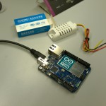
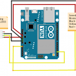
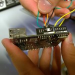
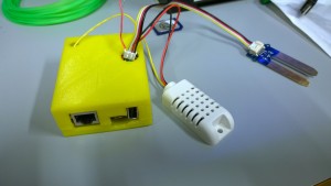
The hardware used consisted of Arduino Yun and two sensors; AM2302 for temperature and air humidity and a Seeedstudio Grove sensor for soil moisture. We chose Arduino Yun because it felt like an easy device to use; it runs a Linux and contains a Wi-Fi chip. All we had to do was to setup it, plug it to a laptop with Arduino IDE and connect the sensors. After that we could just start writing code. Very Easy!

For the Arduino Yun we wrote a simple program that reads the input from the sensors attached to it every 10 minutes. The input from the sensors is then formatted to JSON and pushed to Firebase which is a web service for storing and querying data. The delay between reads from the sensors can be configured to any value that fits the best.

The Web application

The web application was built using Nodejs, ExpressJS and Firebase as the backend. The frontend was built using AngularJS, Angularfire and using D3js to draw the charts. The code can be found from Github (https://github.com/jlehvae/exgreen2k15). The application was deployed to Heroku (https://guarded-mesa-9835.herokuapp.com/).

The most significant challenge of the web application was to correctly visualize the data. For visualization we used Angular directive called Angular-nvD3. The Angular-nvD3 didn’t have very specific instructions on how to format your data so that it is correctly visualized and that’s why we had to take a trial and error approach. Configuring the charts correctly and formatting the data properly can take a while if you don’t have any previous experience with D3js. After we figured out the correct way to input the data, we were getting charts that didn’t look quite right. Soon we found out that we were actually missing a specific CSS file. After adding the missing file everything pretty much started working.

Online Dashboard at Heroku

Online Dashboard at Heroku

3D printing

The final step was 3D printing a case for our Arduino. We had no experience working with a 3D printer before. It was surprising how easy it was to print the case. It turned out the Internet is full of readymade 3D models for different things. It took only a couple of minutes to search for a model that is designed for Arduino Yun. Only problem with the model was that we had two wires that needed holes on top of it so we could have the sensors attached while the Yun is in the case. We made the holes using Tinkercad (https://www.tinkercad.com/). It’s a website that let’s you import and edit 3D models using a web UI and export them back once they are modified.

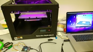
We used Makerbot Replicator 2 as the 3D printer. It was easy to use; just add the file of the model you want to print using the MakerWare and press start (we pretty much used the default values for everything). Printing the case took around 2 hours in total. The top and the bottom part of the case had to be printed separately so the case wouldn’t break apart during printing as there would have been nothing to support the roof of the case. The top part of the case was printed upside down so the roof was supported facing against the floor of the printer.

Sensors and the validity of the data

There were some problems with the moisture sensor as the readings before and after watering a plant were not that different. The plant in question was supposed to be quite dry yet the sensor gave readings of 400 ish (according to Seeedstudio this means that the soil is moist) and after excessive watering the readings only went up by around 40. The fact that our sensor had been used before and appeared quite worn probably had something to do with this.

The setup was tested on multiple occasions by simply turning the device on and manipulating the sensors by

  • touching the moisture sensor
  • putting the moisture sensor in soil and pouring water into it
  • blowing into the humidity/temperature sensor
  • leaving the temp/hum sensor under direct sunshine

What we found out was exactly what you’d expect: the sensors (and thus our charts) correctly reacted to changes in the environment. This didn’t really mean that the data was valid, though. If we had one or two more copies of the sensors we could have tested if they are all giving out same metrics in the same conditions. Now there was no way of knowing if the sensors were accurate or if the data was valid or not.

Continue reading

Exact Greenhouse

Since year 2010 the rooftop of Department of Computer Science has been a busy workaround for scientific experiments at the University of Helsinki.  The location was first used for studying whether it was possible to cool computer servers with the hash Finnish winter air.

Turned out that it was.

pervila

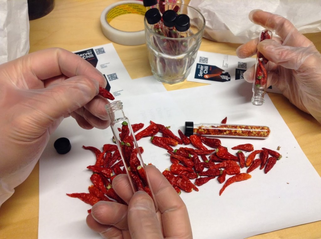
Dr. Mikko Pervilä (DBLP) continued his experiments by building a low-cost greenhouse to accompany his icy server rack. And flocking came the academic chili farmers.

He’s the one in yellow overalls.  Yes we have snow in Finland.

tube

After two years of hot research topics and hefty harvests Dr. Pervilä dismantled the final server from his rack and ended his work at our Department. Future of the research laboratory was left open.


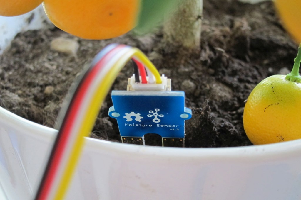
Current prototype uses Grove moisture sensor.


That’s when we took over

On May 2014 we launched opportunity to study what may become the next big thing after the invention of WWW.  Our fresh and green  IOT course  was and will be held in 2015 at the urban rooftop gardening spot with enthusiastic  group of Computer Sciencentists.

This blog tells the small story of the courses arranged 2015-2016, where participants created prototypes for systems for helping the chili growers to work together.

Yours truly,
Hanna Mäenpää
Samu Varjonen
Arto Vihavainen

We’re on Twitter

HEY! PS!

katto

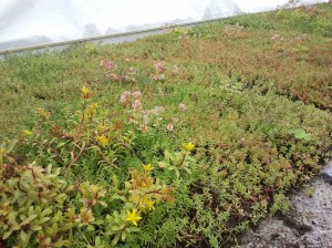
Fifth Dimension  has an ongoing research at the location. They study how green roofs can help urban environments and energy efficiency. Isn’t that awesome? 

BonsaiBox

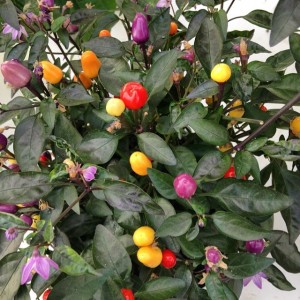
Inspired by Fatalii, I decided to cut down one of my Bolivian Rainbow chili plant which I had kept alive throughout the winter 2013-2014. A chili which has a lot of leaves dehydrates quite a lot of water and therefore placing it into an ordinary bonsai planter just does not appeal to me. I was afraid that the small container did not hold enough humidity and the plant would suffer from recurring droughts, which are exceptionally bad for chilis. Yes they are.

rainbow

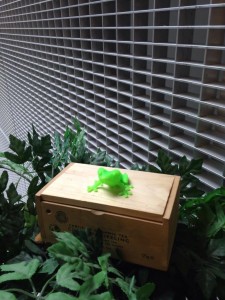
So, the idea of the BonsaiBox with an Arduino Uno followed. I stole an empty tea box from the Department’s coffee room and drilled some holes to it’s back and front panel. I ordered an Adafruit CC3300 Wifi breakout board and while waiting for it to arrive,  printed both a 9v battery holder and a light mount for the Uno to make the installment stable within the box.  And a cute green frog to sit on top.

 bonsailaatikko

I used a “Grove” soil moisture sensor from SeedStudio. Finding the right ranges for different soil states took a couple of days and tries. Resolution of the sensor was with 5v+ from 300…950, which was quite ok for this purpose.  I ended up with three levels:

“I’m OK”
“soil is just a little dry” and
“pour me water or I’ll die”

This is the soil moisture sensor:  It is fit for only 5cm long so it was ok for my purpose with a very small container. The sensor wouldn’t be feasible for bigger ones

I experimented with  RGB leds. I had a common anode lying around. It was fairly confusing to figure what should be given as an input for it. I went  to Partco and bought a cathode and  BOOM, code made simple. I also had a simple photoresistor with a LilyPad buzzer and switch left from my previous projects. I used these parts to enable interaction with a person sitting next to the Bonsaibox. The buzzer really sounds like a frog.


Getting online
Wifi shield arrived, I almost killed it with my bad soldering. But finally, got the parts assembled and started integrating my code from the output experiments with example code of the CC3300 breakout. It worked.

Pseudocode: 

Measure humidity
Send sensor value to Janne’s backend

IF
soil is is humid
    blink blue with RGB LED

ELSE IF
soil is drying out
   blink yellow with RGB LED

ELSE IF
soil is completely dry
blink red with RGB LED
if it has been dry for the whole day
start making a frog-like sound continuously until the plant is
watered.  Play it even louder during the night. Yes, that’s a bit
mean but that’s the way I like it.

ELSE
wait for a while and measure the humidity again.

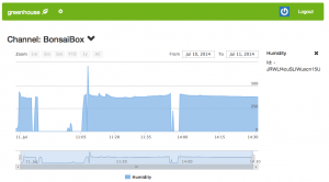
The data really nice in Janne’s EGH-chart. Thank you for the awesome work, man.

bonsaibox_chart

Learnings:

My prior knowledge on microcontrollers was limited to one successful and one failed project with Lilypad (I couldn’t figure anything meaningful to do so I trashed the whole project). I did know how to code but hadn’t done it in years.

So the outcome: inside the Bonsaibox.. Oh it’s ugly. Looks like a homemade bomb. I didn’t order a sensor shield  which was a bad mistake. I had to take apart all the nice plug&play connectors and solder a lot.  After getting the hardware together it was really hard to keep the wires attached. People. Don’t save from the wrong place. Get a shield.

Programming was fun. There were ready libraries for the WiFi and it was easy to integrate them with my code. I got a lot of confidence as a coder from this project.I learned to Google from the right places.  I CAN! And I will do it again.

Internet of Things: Temperatures

The greenhouse has an existing temperature sensor setup consisting of DS18B20 1-Wire temperature sensors. They are fitted inside RJ11 female-to-female extenders, which is convenient since arbitrarily many sensors can be added by connecting many of them together via RJ11 cables.  There should be enough of those sensors to build an heatmap of the greenhouse for example. Those sensors could be read by bit-banging on one of the two fast GPIOs on the Galileo, or maybe a proper USB-to-1Wire converter is actually required for those long cables.

Internet of Things: The Magical Flower Pot

If you are lacking a green thumb you probably know what dying plants look like. Most of us like flowers, but keeping them alive and well can sometimes be challenging.

We are building a solution for that. Our magical flower pot includes sensors that measure temperature and moisture level of the soil. If those levels drop below predefined levels, pot sends you an e-mail – heck, it can even tweet if that is preferred.

Current prototype uses Grove moisture sensor.

Current prototype uses Grove moisture sensor.

Naturally we are building a mobile application for the flower pot too. With the app you can monitor the moisture levels and adjust all necessary parameters since different plants need different growing conditions.

Electric Imp is our sorcerer.

Electric Imp is our sorcerer.

Prototype is being built using Electric Imp and few different moisture sensors. One of the challenges will be power consumption. We are aiming for low-power solution. Ideally one 9v battery should last for weeks.

Measured data is stored to the cloud.

Measured data is stored to the cloud.


Internet of Things: Paranoid Gardener

I think it’s fair to say that my project turned out to be rather simplistic. After some initial hardware-pondering and debugging (thanks Samu for expertise), it turned out that element14’s explore-nfc expansion board was the choice to go with. The expansion board along with a Raspberry Pi model B + a usb wifi dongle was the hardware arsenal on top of which this NFC-reading application was built.

Starting out with the task I suspected to be the most intensive, I set out to write a client on top of the Raspberry Pi in C. This client would be responsible for 1) reading nfc tag id’s and 2) uploading the tag id’s along with timestamps to a web-backend. At first, I had a design that employed TCP sockets and a little bit of linux signalling and forking in my mind. Wanting to add some new elements to the mix, I was going to write the networking part using a message-queuing library called ZeroMQ. ZeroMQ would make it easy to add encryption and some nice network designs to the project.Knowing that ZeroMQ was written in C++, I assumed that would be a not-too-different (and not any less well documented!) C-API available. Well, it turned out that due to the socket management that ZeroMQ does, it isn’t straightforward to fork the process using standard Linux system calls. From how I got it, ZeroMQ sockets live in the realm of a ZeroMQ context – this context cannot simply be shared among multiple threads or processes. Instead, ZeroMQ provides it’s own thread handling functionality, for which I deemed the CZMQ’s (a ZeroMQ C-API implementation) documentation to be insufficient. Balancing between learning and getting the project wrapped up, I decided to code the networking parts of the client using standard linux socket APIs.

Another thing on the client side that struck me was the question of how to give feedback to a NFC-keychain swinging user. I figured that the most obvious solutions would be either using a speaker or blinking LED lights. To keep things simple, the final project uses the one and only controllable green LED light that’s on board a Raspberry Pi. No user friendliness here, but it works.

To conclude, a little bit of the www-backend. It’s divided into two parts: 1) a TCP server listening for incoming nfc-id &  timestamp tuples and 2) an actual www-server, both of which are implemented using Node.JS and communicate through MongoDB. The www-server uses Twitter bootstrap for templating and Angular.JS + jQuery for implementing some AJAX functionality.Initially, the plan was togo and only use Angular.JS (and the minimalistic jQuery implementation that comes along with it). I also wanted to use Twitter bootstrap’s modals to increase the UI-friendliness when letting the user see and make comments that are associated with timestamped NFC id readings. Angular.JS and Twitter bootstrap modals did not seem to work together out of the box (going deeper into this would’ve defocused the project), so I decided to mix in a little bit of jQuery. Well, it ain’t fancy, but it works.

The original post is below:

Gardening and crops are a serious business. Rumor has it that some players have even gone as far as patenting their long-cultivated and slightly modified plants and the seeds they produce. Gees! It is clear that such an industry that holds secrets more valuable than the welfare of the gardeners themselves needs adequate protection mechanisms, and fast.

My project’s called the Paranoid Gardener, but instead of Paranoid Androids, the platform it will be built on is a Raspberry PI.  As the process of evaluating the requirements to wholly secure such a vital system (everybody has to eat, right?) is still continuing, the exact plan isn’t 100% fool-proof yet.. but it will at least involve an NFC authentication system. Besides the authentication of users, the system should aim at tracking the approximate flow of visitors to the garden by recording the times the door has been opened.  If there’s time, it would be interesting to take a look at nearby mobile device detection by catching WIFI probes. On the other hand, the system could interact with its user by sending messages over BT. Minimally, the system should publish its authentication data to web. We shall see how the final design comes together.

One thing that isn’t clear at this stage is the access control and management of NFC tags that are associated with the system. A promising way could be the running of a web backend on the PI through which commands could be sent in order to create new NFC tags, or remove old ones. This will be a point to be considered later.